Rainbow Electronics DS26503 User Manual
Page 83
DS26503 T1/E1/J1 BITS Element
83 of 123
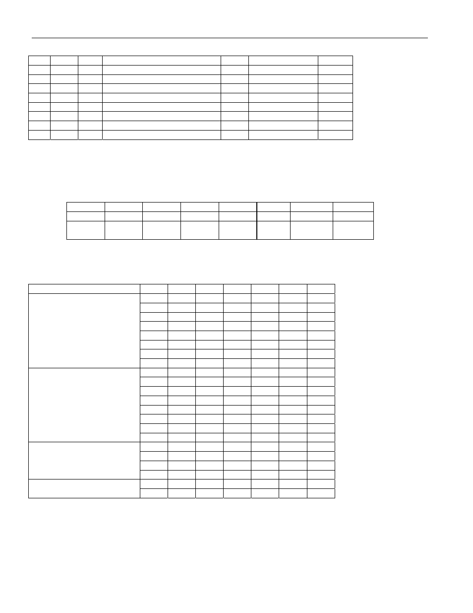
T1 Mode
L2
L1
L0
APPLICATION
N (1)
RETURN LOSS
Rt (1)
0
0
0
DSX-1 (0 to 133 feet)/0dB CSU
1:2
N.M.
0
0
0
1
DSX-1 (133 to 266 feet)
1:2
N.M.
0
0
1
0
DSX-1 (266 to 399 feet)
1:2
N.M.
0
0
1
1
DSX-1 (399 to 533 feet)
1:2
N.M.
0
1
0
0
DSX-1 (533 to 655 feet)
1:2
N.M.
0
1 0 1
Reserved
1 1 0
Reserved
1 1 1
Reserved
Register Name:
TLBC
Register Description:
Transmit Line Build-Out Control
Register Address:
34h
Bit
# 7 6 5 4 3 2 1 0
Name — AGCE GC5 GC4 GC3 GC2 GC1 GC0
Default
0 0 0 0 0 0 0 0
HW
Mode
0 0 0 0 0 0 0 0
Bit 0–5/Gain Control Bits 0–5 (GC0–GC5). The GC0 through GC5 bits control the gain setting for the non-automatic gain
mode. Use the tables below for setting the recommended values. The LB (line build-out) column refers to the value in the
L0–L2 bits in LIC1 (Line Interface Control 1) register.
NETWORK
MODE
LB GC5 GC4 GC3 GC2 GC1 GC0
0 1 0 0 1 1 0
1 0 1 1 0 1 1
2 0 1 1 0 1 0
3 1 0 0 0 0 0
4 1 0 0 1 1 1
5 1 0 0 1 1 1
6 0 1 0 0 1 1
T1, Impedance Match Off
7 1 1 1 1 1 1
0 0 1 1 1 1 0
1 0 1 0 1 0 1
2 0 1 0 1 0 1
3 0 1 1 0 1 0
4 1 0 0 0 1 0
5 1 0 0 0 0 0
6 0 0 1 1 0 0
T1, Impedance Match On
7 1 1 1 1 1 1
0 1 0 0 0 0 1
1 1 0 0 0 0 1
4 1 0 1 0 1 0
E1, Impedance Match Off
5 1 0 1 0 0 0
0 0 1 1 0 1 0
E1, Impedance Match On
1 0 1 1 0 1 0
Bit 6/Automatic Gain Control Enable (AGCE).
0 = use Transmit AGC, TLBC bits 0–5 are “don’t care”
1 = do not use Transmit AGC, TLBC bits 0–5 set nominal level
Bit 7/Unused, must be set = 0 for proper operation.