Hardware controller interface, Transmit clock source, Internal termination – Rainbow Electronics DS26503 User Manual
Page 26: Ransmit, Lock, Ource, Nternal, Ermination, Table 6-1. transmit clock source, Table 6-2. internal termination
DS26503 T1/E1/J1 BITS Element
26 of 123
6. HARDWARE CONTROLLER INTERFACE
In Hardware Controller mode, the parallel and serial port pins are reconfigured to provide direct access to
certain functions in the port. Only a subset of the device’s functionality is available in hardware mode.
Each register description throughout the data sheet indicates the functions that may be controlled in
hardware mode and several alarm indicators that are available in both hardware and processor mode.
Also indicated are the fixed states of the functions not controllable in hardware mode.
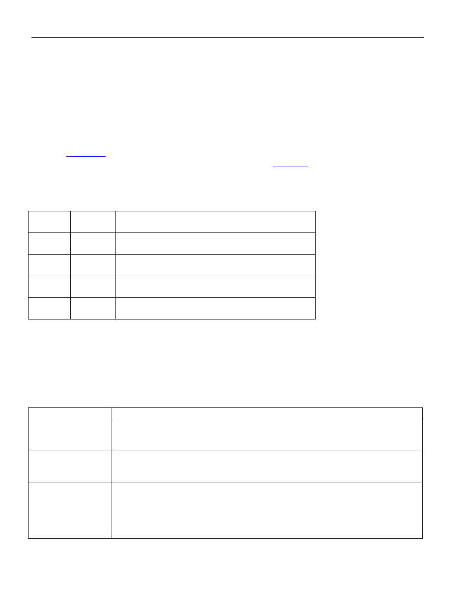
6.1 Transmit Clock Source
Refer to
. In Hardware Controller mode, the input to the TX PLL is always TCLK PIN. TX
CLOCK is selected by the TCSS0 and TCSS1 pins, as shown in
. The PLL_OUT pin is always
the same signal as select for TX CLOCK. If the user wants to slave the transmitter to the recovered
clock, then the RCLK pin must be tied to the TCLK pin externally.
Table 6-1. Transmit Clock Source
TCSS1
PIN 31
TCSS0
PIN 63
TRANSMIT CLOCK SOURCE
0
0
The TCLK pin is the source of transmit clock.
0
1
The PLL_CLK is the source of transmit clock.
1 0
The scaled signal present at MCLK as the transmit
clock.
1
1
The signal present at RCLK is the transmit clock.
6.2 Internal Termination
In Hardware Controller mode, the internal termination is automatically set according to the receive or
transmit mode selected. It can be disabled via the TITD and RITD pins. If internal termination is enabled
in E1 mode, the E1TS pin is use to select 75
W or 120W termination. The E1TS pin applies to both
transmit and receive.
Table 6-2. Internal Termination
PIN NAME
FUNCTION
TITD
PIN 5
Transmit Internal Termination Disable. Disables the internal transmit
termination. The internal transmit termination value is dependent on the state of
the TMODEx pins.
RITD
PIN 6
Receive Internal Termination Disable. Disables the internal receive
termination. The internal receive termination value is dependent on the state of
the RMODEx pins.
E1TS
PIN 9
E1 Termination Select. Selects 120
W or 75W internal termination when one of
the E1 modes is selected and internal termination is enabled. IF E1 is selected for
both transmit and receive, then both terminations will be the same.
0 = 75
W
1 = 120
W