E1 framer/formatter control registers, E1 control registers, E1 c – Rainbow Electronics DS26503 User Manual
Page 46: Ontrol, Egisters, 1 e1 control registers
DS26503 T1/E1/J1 BITS Element
46 of 123
9. E1 FRAMER/FORMATTER CONTROL REGISTERS
The E1 framer portion of the DS26503 is configured via a set of two control registers. Typically, the
control registers are only accessed when the system is first powered up. Once the DS26503 has been
initialized, the control registers will only need to be accessed when there is a change in the system
configuration. There is one receive control register (E1RCR) and one transmit control register (E1TCR).
There are also two information registers and a status register, as well as an interrupt mask register. Each
of these registers is described in this section.
9.1 E1 Control Registers
Register Name:
E1RCR
Register Description:
E1 Receive Control Register
Register Address:
1Dh
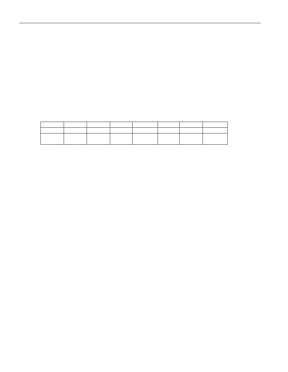
Bit
# 7 6 5 4 3 2 1 0
Name —
RLOSA
RHDB3
— — FRC
SYNCE
RESYNC
Default
0 0 0 0 0 0 0 0
HW
Mode
0 0
HBE
PIN 55
0 0 0 0 0
Bit 0/Resync (RESYNC). When toggled from low to high, a resync is initiated. Must be cleared and set again for a subsequent
resync.
Bit 1/Sync Enable (SYNCE).
0 = auto resync enabled
1 = auto resync disabled
Bit 2/Frame Resync Criteria (FRC).
0 = resync if FAS received in error three consecutive times
1 = resync if FAS or bit 2 of non-FAS is received in error three consecutive times
Bit 3/Unused, must be set = 0 for proper operation.
Bit 4/Unused, must be set = 0 for proper operation.
Bit 5/Receive HDB3 Enable (RHDB3).
0 = HDB3 disabled
1 = HDB3 enabled
Bit 6/Receive Loss Of Signal (RLOS). Alternate Criteria (RLOSA). Defines the criteria for a Receive Loss Of Signal
condition.
0 = RLOS declared upon 255 consecutive zeros (125µs)
1 = RLOS declared upon 2048 consecutive zeros (1ms)
Bit 7/Unused, must be set = 0 for proper operation.