Lenovo ThinkServer RD650 User Manual
Page 97
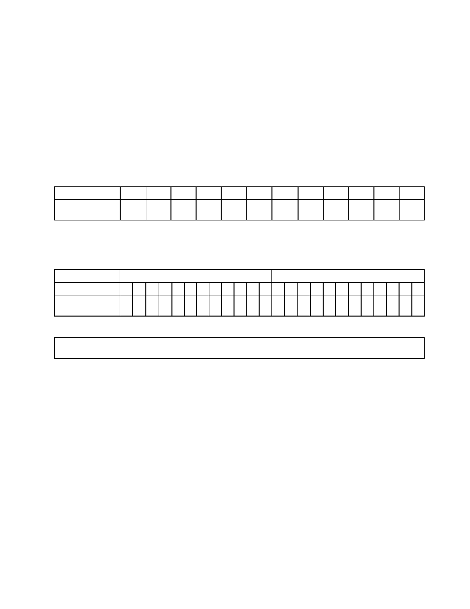
Memory module installation order in lockstep mode
In lockstep mode, the RAS features are available. For more information about the RAS features, refer to the
related section in “Features” on page 7.
Notes:
• All memory modules to be installed must be the same type with the same capacity, frequency, voltage,
and number of ranks.
• All memory modules must be installed in pairs.
The following table explains the memory module installation order for servers that have only one
microprocessor (CPU1) installed.
Table 10. Memory module installation order in lockstep mode for servers with one microprocessor
CPU1 DIMM
A1
A2
A3
B1
B2
B3
C1
C2
C3
D1
D2
D3
DIMM installation
order
1
3
5
1
3
5
2
4
6
2
4
6
The following table explains the memory module installation order for servers that have two microprocessors
(CPU1 and CPU2) installed.
Table 11. Memory module installation order in lockstep mode for servers with two microprocessors
CPU1 DIMM
CPU2 DIMM
A1 A2 A3 B1 B2 B3 C1 C2 C3 D1 D2 D3 A1 A2 A3 B1 B2 B3 C1 C2 C3 D1 D2 D3
DIMM installation
order
1
1
9
3
3
11 5
5
13 7
7
15 2
2
10 4
4
12 6
6
14 8
8
16
Installing a memory module
Attention: Do not open your server or attempt any repair before reading and understanding “Safety information”
on page iii and “Guidelines” on page 67.
Before you begin, print all the related instructions or ensure that you can view the PDF version on another
computer for reference.
Notes:
• Ensure that you consider and follow the memory module installation rules when performing the operation.
See “Memory module installation rules” on page 79.
• Use any documentation that comes with the memory module and follow those instructions in addition to
the instructions in this topic.
To install a memory module, do the following:
1. Remove all media from the drives and turn off all attached devices and the server. Then, disconnect all
power cords from electrical outlets and disconnect all cables that are connected to the server.
2. Prepare your server. See “Removing or extending the server from the rack cabinet” on page 69.
3. Remove the server cover. See “Removing the server cover” on page 69.
4. Remove the cooling shroud. See “Removing and reinstalling the cooling shroud” on page 72.
5. Locate the memory slots on the system board and read the memory module installation rules. See
“Memory module installation rules” on page 79. Remove the memory dummy if necessary.
83