A-119 – Yaskawa MP2300S Basic Module User Manual
Page 441

Appendix G MSG-SND/MSG-RCV Functions (Ethernet)
G.3 Communication Buffer Channel
A-119
Appendices
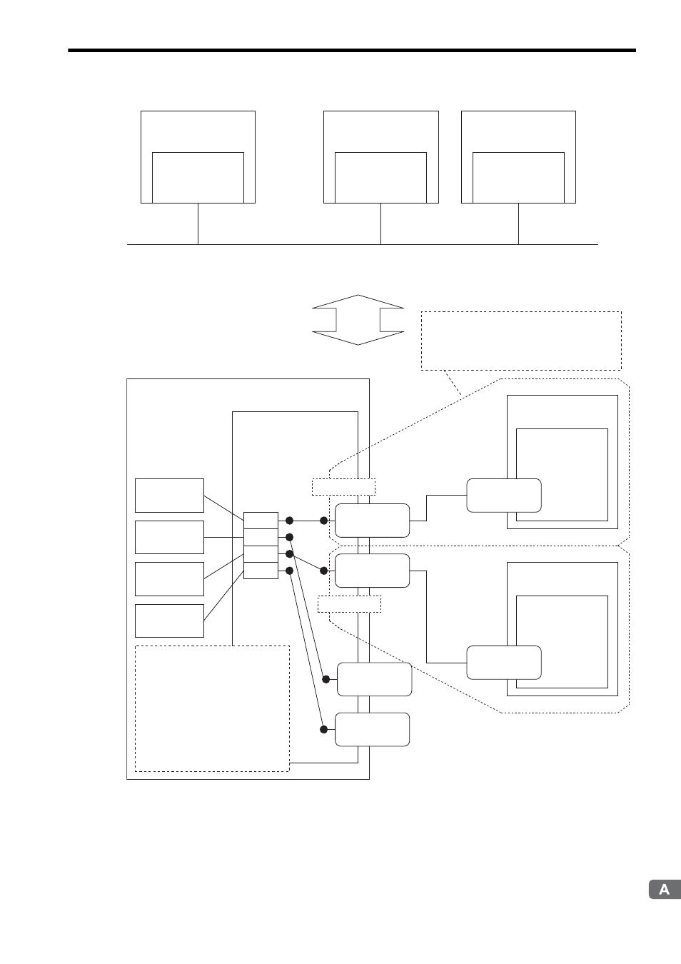
Fig. G.15 Schematic Diagram for Communication Buffer Channel
MP2300S
Ethernet
Local IP Address
192.168.1.x
Remote device #1
Ethernet
Remote IP Address
192.168.1.y
Remote device #2
Ethernet
Remote IP Address
192.168.1.z
Ethernet
Network block diagram
MP2300S
* CNO: Connection number
Note: Maximum number of connections=4
Automatic
Receive
MSG-SND
Function
MSG-SND
Function
MSG-RCV
Function
1
2
3
4
Ethernet (218IFA)
Local IP Address
192.168.1.x
CNO* = 01
CNO* = 02
Port number
10010
Port number
10020
Port No.
10030
Port No.
10040
Port No.
20020
Connection setting
- UDP
- Extended
MEMOBUS
- BIN
Connection setting
- TCP
- MELSEC
- ASCII
Remote device #2
Ethernet
Remote IP Address
192.168.1.z
Port No.
20010
Remote device #1
Ethernet
Remote IP Address
192.168.1.y
The connection is set in the 218IFA
Parameter Setting Window of the MPE720
Module Configuration Definition Window.
Communication
buffer channel
The communication buffer
channel is associated with
the connection by setting
the input item "Ch-No"
(communication buffer channel
number) of the MSG-SND/
MSG-RCV function and
PARAM02 (connection number)
in Param (parameter list).
