3 operation, 1 input/output register, 1 ) master side input/output data – Yaskawa MP2300S Basic Module User Manual
Page 287

7.3 Operation
7.3.1 Input/Output Register
7-9
Slave CPU Synchronous Function
7.3 Operation
7.3.1 Input/Output Register
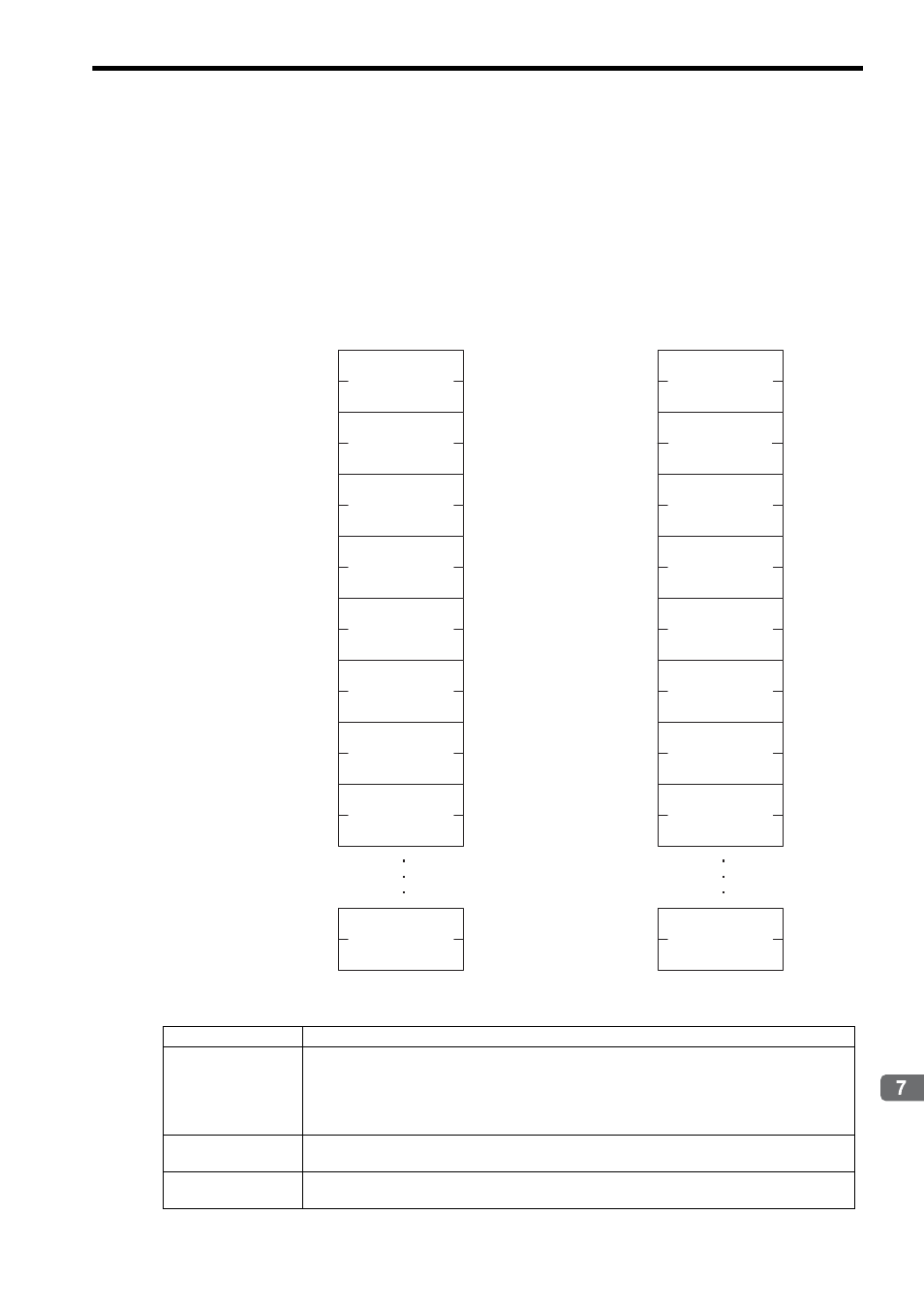
This section describes the details of the input/output register configured in the link assignment.
( 1 ) Master Side Input/Output Data
Input data details
Item
Description
Scan Counter
One byte of area which allows a master side application to check a value configured and updated by a
slave side application. It is used for the following purposes:
• Checks the update of input data from MP2300S.
• Determines the MP2300S behavior (in operation/in pause).
Note that the use of this area is optional.
Slave Status
Status of MECHATROLINK transmission unit of MP2300S.
The configuration is shown on the subsequent page:
Data
Up to 6 words of data area for MECHATROLINK-II (17 Byte) and up to 13 words of data area for
MECHATROLINK-II (32 Byte) are available.
Low
High
Low
High
Low
High
Low
High
Low
High
Low
High
7 6 5 4 3 2 1 0
7 6 5 4 3 2 1 0
IW
+0
IW
+1
IW
+2
IW
+3
IW
+4
IW
+5
IW
+6
IW
+7
IW
+14
OW
+0
OW
+1
OW
+2
OW
+3
OW
+4
OW
+5
OW
+6
OW
+7
OW
+14
[Input register]
Scan counter used
by system
Slave status used
by system
Data 1
Data 2
Data 3
Data 4
Data 5
Data 6
Low
High
Low
High
Low
High
Low
High
Low
High
Low
High
Data 1
Data 2
Data 3
Data 4
Data 5
Data 6
Data 13
Low
High
Data 13
Low
High
[Output register]
Scan counter unused
Unused
Unused
