1 ) external appearance ( 2 ) indicators, 00 23 s – Yaskawa MP2300S Basic Module User Manual
Page 34
2.2 Basic Module
2.2.2 External Appearance, LED Indicators, and Switch Settings
2-8
2.2.2 External Appearance, LED Indicators, and Switch Settings
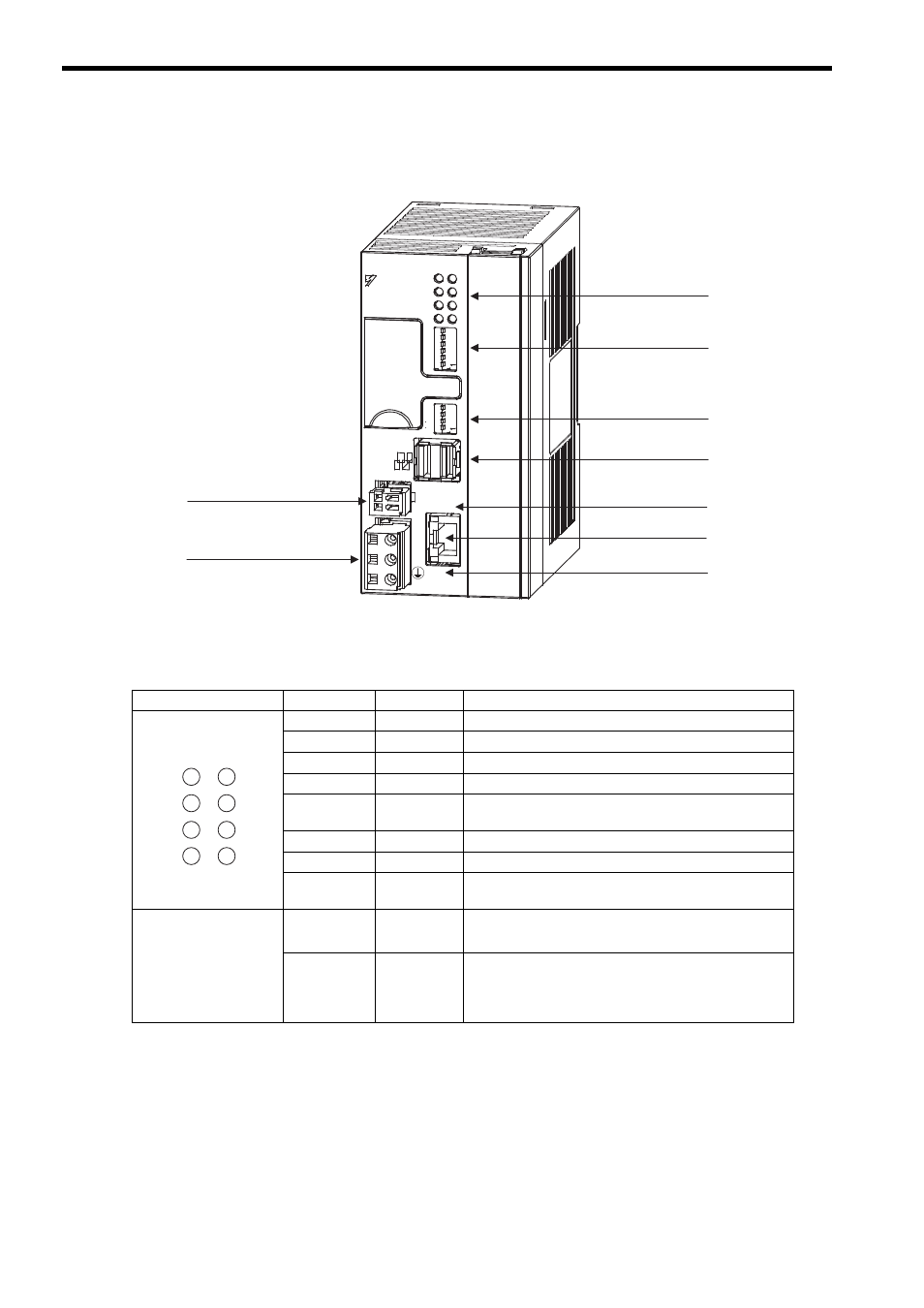
( 1 ) External Appearance
( 2 ) Indicators
The following table shows the indicators that show the operating status of the Basic Module and error information.
For details on indicator meanings, refer to 9.2 LED Indicator Meanings .
MP
/
E
thernet
LINK
00
23
S
&%
&%
8
4.;
176
0V
;#5-#9#
6'56
4&;
#./
/6:
64:
470
'44
$#6
+2
59
59
10
10
%0()
+06
572
/10
5612
$#66'4;
M-
I/II
'
'6'56
+06
01
01
LED 1 indicators
DTP switch (SW1)
DTP switch (SW2)
MECHATROLINK
connector
LED 2 indicator
Ethernet connector
LED 2 indicator
Power supply connector
RLY OUT connector
Indicator
Color
Status
RDY
Green
Lit during normal operation.
RUN
Green
Lit during execution of user program.
ALM
Red
Lit or blinks when warning occurs.
ERR
Red
Lit or blinks when malfunction occurs.
MTX
Green
Lit when submitting MECHATROLINK-I/ MECHA-
TROLINK-II data.
BAT
Red
Lit during battery alarm.
TRX
Green
Lit when transmitting and receiving Ethernet data.
IP
Green
Lit after IP address setting is set
Blinks when Ethernet port fails
• LINK
• 100M
(Part of Ethernet connec-
tor)
LINK
Yellow
Lit when connected to Ethernet.
100M
Green
Lit when transmitting data at 100 Mbps or during automatic
negotiation at 100 Mbps.
Not lit when transmitting data at 10 Mbps or during auto-
matic negotiation at 10 Mbps.
RDY
ALM
MTX
RUN
ERR
BAT
TRX
IP