6 system connection example, Mounting and wiring, Vac power supply – Yaskawa MP2300S Basic Module User Manual
Page 116: Terminating resistance, I/o module ground resistance: 100 ω or less, Panel programming device, Machine i/o terminating resistor

3.2 Basic Module Connections
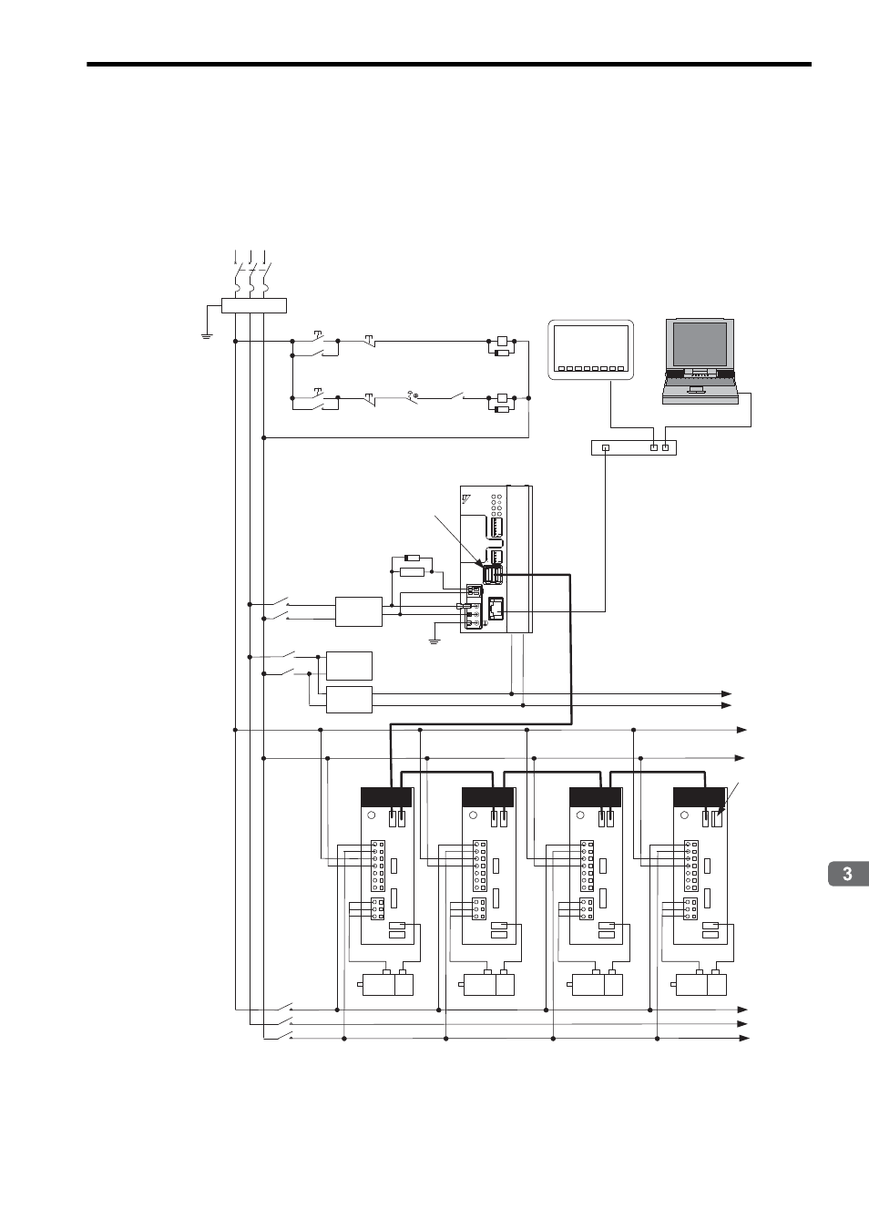
3.2.6 System Connection Example
3-25
Mounting and Wiring
3.2.6 System Connection Example
The following diagram shows a connection example of a system using the MP2300S.
The following diagram shows a 200-VAC power supply example.
Note: elect the SERVOPACK, 24-VDC power supply to use in accordance with the input power supply specifi-
cation.
2MC
1MC
1MC
2MC
1MC
SA
SA
R S T
1MCCB
RA1
SA
RA1
㧗24 V
㧜
24
V
SGDS
L1
L2
L1C
L2C
B1/
B2
㧙
U
V
W
C
N
3
C
N
6
C
N
1
ޓޓޓ
ޓޓޓ
ޓޓޓ
R
S
T
㧞MC
㧝MC
r
t
PG
M
PG
M
PG
M
PG
M
RA1
&%
4.;
176 'VJGTPGV
&%
8
.+0-
/
0V
MP2300S
;#5-#9#
6'56
4&;
#./
/6:
64:
470
'44
$#6
+2
59
59
/10
%0()
+06
572
5612
$#66'4;
㪧㪦㪮㪜㪩
'
M-
I/II
+0+6
01
01
'6'56
*1
*1
*2
*1
*1
SA: Surge absorber (for switching surge)
*2 RAI: CPU RUN output
200-VAC power supply
Noise filter
Turn ON the
control power
Shut OFF the
control power
Turn ON the
servo power
Shut OFF the
servo power
Emergency
stop
Terminating resistance
24-VDC
power
supply 1
24-VDC
power
supply 2
I/O Module
Ground resistance:
100
Ω or less
Load
equipment
Panel
Programming device
HUB
Machine
I/O
Terminating
resistor
SGDS
SGDS
SGDS
L1
L2
L1C
L2C
B1/
B2
㧙
C
N
3
C
N
6
C
N
1
U
V
W
L1
L2
L1C
L2C
B1/
B2
㧙
C
N
3
C
N
6
C
N
1
U
V
W
L1
L2
L1C
L2C
B1/
B2
㧙
C
N
3
C
N
6
C
N
1
U
V
W
