6 restrictions for feedback pulse inputs – Yaskawa JAPMC-MC2300 User Manual
Page 44
2.6 Restrictions for Feedback Pulse Inputs
2.6.1 Restrictions for SERVOPACK Pulse Output Frequency
2-18
2.6 Restrictions for Feedback Pulse Inputs
2.6.1 Restrictions for SERVOPACK Pulse Output Frequency
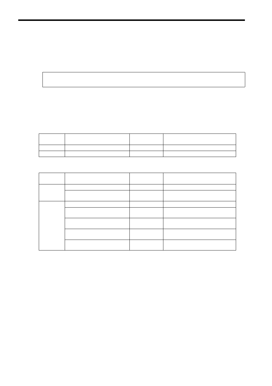
The upper limit to the SERVOPACK pulse output frequency is shown below.
However; Motor Speed at a Divided Output Pulse Frequency of 1.6 MHz = 1.6
× 10
6
× 60 ÷ Pn212 set value
The following tables show the relationship between the number of encoder bits and the maximum speed for a pulse fre-
quency of 1.6 MHz output by
Σ-II/Σ-III/Σ-V SERVOPACK.
Application must be within the ranges shown in these tables when a
Σ-II/Σ-III/Σ-V SERVOPACK is connected to the
SVA-01 Module.
When connecting a
Σ-II SERVOPACK
When connecting a
Σ-III or a Σ-V SERVOPACK
Upper Limit (actual value) of Phase-A/B Divided Output Pulse Frequency fo
Σ-II/Σ-III/Σ-V SERVOPACK =
1.6 MHz (before multiplication)
Encoder Bits
Pn201 Setting Range
Pn201 Setting
Example
Motor Speed (min
-1
) at a Divided Output
Pulse Frequency of 1.6 MHz
17 bits
16 to 16384 (in increments of pulses)
16384
6000
20 bits
16 to 16384 (in increments of pulses)
16384
6000
Encoder Bits
Pn212 Setting Range
Pn212 Setting
Example
Motor Speed (min
-1
) at a Divided Output
Pulse Frequency of 1.6 MHz
17 bits
16 to 16384 (in increments of pulses)
16384
6000
16386 to 32768 (in increments of
pulses)
32768
3000
20 bits
16 to 16384 (in increments of pulses)
16384
6000
16386 to 32768 (in increments of
pulses)
32768
3000
32772 to 65536 (in increments of
pulses)
65536
1500
65544 to 131072 (in increments of
pulses)
131072
750
131088 to 262144 (in increments of
pulses)
262144
375