Yaskawa JAPMC-MC2300 User Manual
Page 163

7.2 Motion Command Details
7.2.3 Zero Point Return (ZRET)
7-23
7
Motion Commands
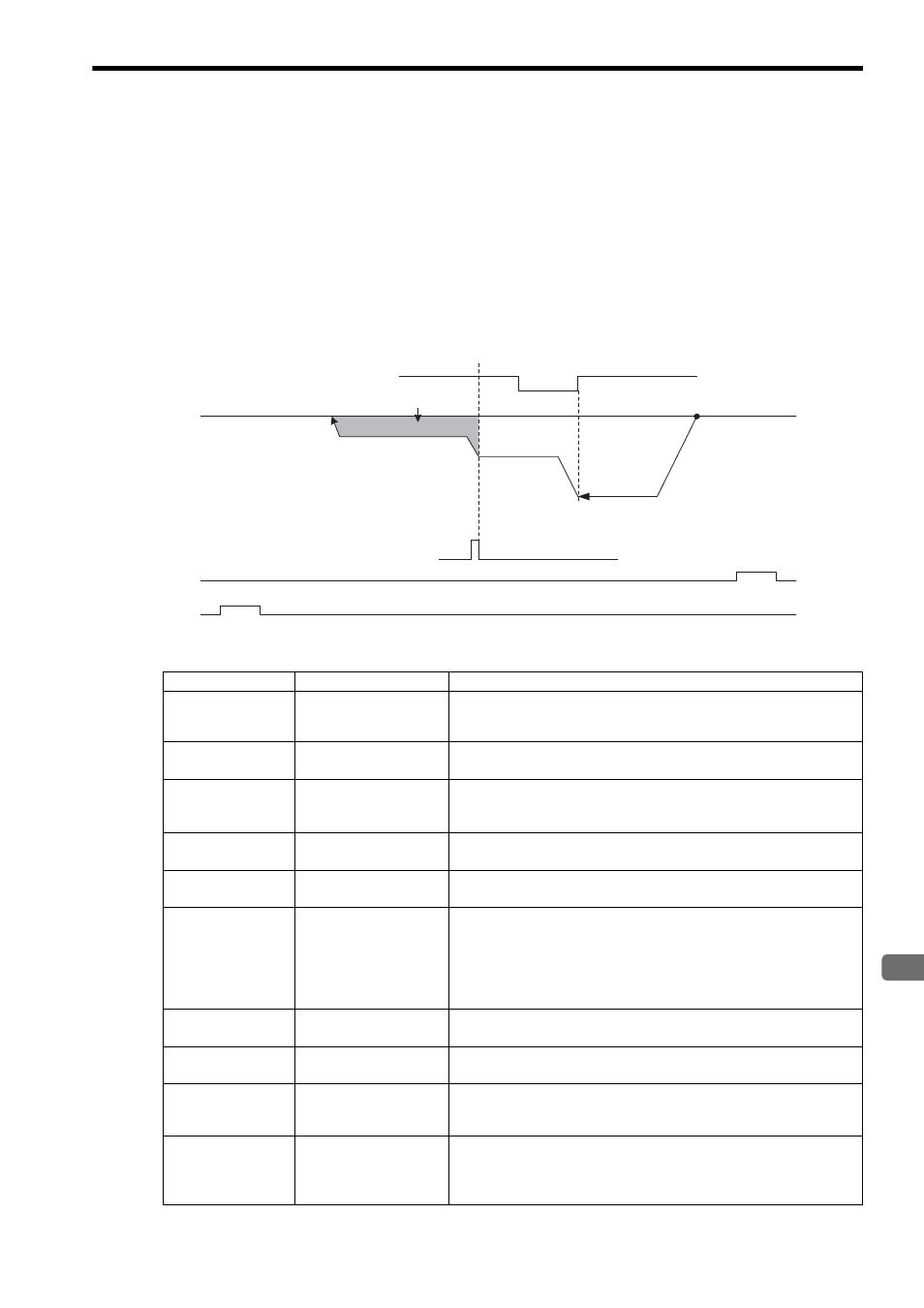
[ c ] DEC1 + ZERO Signal Method (OW
3C = 2)
Operation after Zero Point Return Starts
Travel is started at the zero point return speed in the direction specified in the parameters.
When the rising edge of the DEC1 signal is detected, the speed is reduced to the approach speed.
When the rising edge of the ZERO signal is detected after passing the DEC1 signal at the approach speed, the speed is
reduced to the creep speed and positioning is performed.
When the positioning has been completed, a machine coordinate system is established with the final position as the
zero point.
The moving amount after the ZERO signal is detected is set in the Zero Point Return Travel Distance (OL
42).
If an OT signal is detected during the zero point return operation, an OT alarm will occur.
Parameters to be Set
Parameter
Name
Setting
Fixed Parameter
No. 1, Bit 5
Deceleration LS
Inversion Selection
Set whether or not to invert the polarity of DI_5 signal used as DEC1 signal.
However, the Zero Point Return Deceleration LS Signal (OW
05, bit 8)
will not be inverted even if this bit is set to 1 (invert).
Fixed Parameter
No. 21, Bit 0
Deceleration LS Signal
Selection
Select the signal to be used as DEC1.
0: OW
05, bit 8, 1: DI_5
OW
05, Bit 8
Zero Point Return
Deceleration LS Signal
(DEC1)
Used to input DEC1 signal from the ladder program when the bit 0 of fixed
parameter No.21 is 0.
OW
09, Bit 3
Zero Point Return
Direction Selection
Set the zero point return direction.
0: Reverse rotation (default), 1: Forward rotation
OL
10
Speed Reference
Setting
Set the speed to use when starting a zero point return.
Only a positive value can be set; a negative value will result in an error.
OW
18
Override
This parameter allows the Zero Point Return speed to be changed without
changing the Speed Reference Setting (OL
10). Set the speed as a per-
centage of the Speed Reference Setting. This setting can be changed during
operation.
Setting range: 0 to 32767 (0% to 327.67%) Setting unit: 1 = 0.01%
Example: Setting for 50%: 5000
OW
3C
Zero Point Return
Method
2: DEC1 + ZERO Signal Method
OL
3E
Approach Speed
Set the speed to use after detecting the DEC1 signal.
Only a positive value can be set; a negative value will result in an error.
OL
40
Creep Rate
Set the speed to use after detecting the ZERO signal after passing the DEC1
signal.
Only a positive value can be set; a negative value will result in an error.
OL
42
Zero Point Return Travel
Distance
Set the travel distance from the point where the ZERO signal is detected
after passing the DEC1 signal.
If the sign is positive, travel will be toward the zero point return direction; if
the sign is negative, travel will be away from the zero point return direction.
DEC1 signal (DI_5 or OW
05, bit 8)
N-OT (DI_4)
P-OT (DI_3)
Start
Zero Point
ZERO signal (DI_2)
Zero Point Return
Travel Distance
(OL
42)
Creep Rate
(OL
40)
Approach speed
(OL
3E)
Speed Reference Setting
(OL
10)
