3 axis stopping operation at alarm occurrence, 4 processing after an alarm occurs, 1 ) monitoring alarms – Yaskawa JAPMC-MC2300 User Manual
Page 314: 2 ) clearing software limit alarms
11.3 Software Limit Function
11.3.3 Axis Stopping Operation at Alarm Occurrence
11-14
11.3.3 Axis Stopping Operation at Alarm Occurrence
The way the axis stops at occurrence of alarm differs depending on the motion command that is being executed as
shown in the table below.
The software limit settings is disabled for ZRET operation.
11.3.4 Processing after an Alarm Occurs
( 1 ) Monitoring Alarms
If an axis exceeds a software limit, a Positive/Negative Soft Limit (Positive/Negative Software Limit) alarm will occur.
This alarm can be monitored in the monitoring parameter (IL
04).
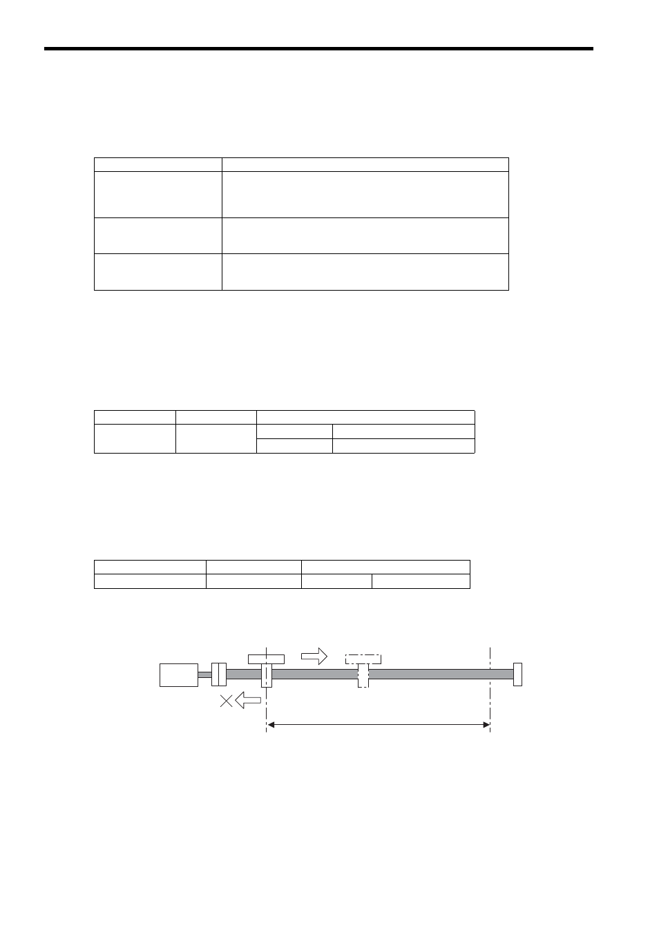
( 2 ) Clearing Software Limit Alarms
Clear software limit alarms using the procedure below.
1.
Set the Clear Alarm bit to 1 in the RUN Command Setting (OW
00, bit F) to clear the alarm.
The alarm (IL
04) will be cleared.
2.
Use the FEED or STEP command to return past the software limit.
Motion Command
Stop Operation
POSING
EX_POSING
FEED
STEP
The axis will start decelerating before the software limit position and stop
at the software limit position.
INTERPOLATE
ENDOF_INTERPOLATE
LATCH
The pulse distribution command will stop executing at the software limit
position. The Servo will perform an emergency stop.
VELO
TRQ
PHASE
The axis will start decelerating the software limit position and stop
beyond the software limit position.
Name
Parameter No.
Meaning
Alarm
IL
04
Bit 3:
Positive Direction Software Limit
Bit 4:
Negative Direction Software Limit
Name
Parameter No.
Meaning
RUN Command Setting
OW
00
Bit F:
Alarm Clear
Commands will be received in the return direction.
Servo-
motor
An alarm will occur again if a command is
given in the direction of the software limit
that was activated.
Software Limit,
lower limit
Software Limit,
upper limit