3 cn1 and cn2 connector pin arrangement – Yaskawa JAPMC-MC2300 User Manual
Page 38
2.4 SVA-01 Module Connections
2.4.3 CN1 and CN2 Connector Pin Arrangement
2-12
2.4.3 CN1 and CN2 Connector Pin Arrangement
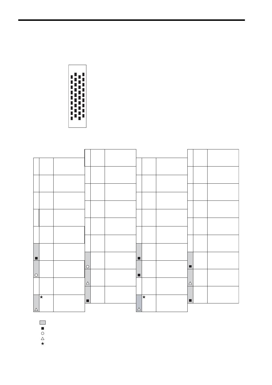
The following figures show the 36-pin arrangement, each pin name and assignment for connectors CN1 and CN2.
Pin Arrangement Viewing from the Cable-Side
19
20
1
2
35
36
17
18
1
SG
Ground
(analog)
2
AO_0
(
NREF
)
General-purpose
analog output 0
(Speed reference output)
3
PA
5-V differential
phase-A
pulse input (+)
4
PAL
5-V differential
phase-A
pulse input (
−)
6
PCL
5-V differential
phase-C
pulse input (
−)
5
PC
5-V differential
phase-C
pulse input (+)
7
SG
Ground
8
AI_0
General-purpose
analog input 0
(Feedback speed
monitor input)
9
AO_1
(
TREF
)
General-purpose
analog output 1
(Torque reference output)
10
0V
(For 24 V)
0 V (for 24 V) output
11
0V
(For 24 V)
0 V (for 24 V) output
DO_2
(
PCON
)
General-purpose
output DO_2
(P action reference output)
13
DO_4
General-purpose
output DO_4
14
DO_3
General-purpose
output DO_3
15
DI_3
(
P-OT
)
General-purpose
input DI_3
(Positive overtravel input)
16
+24V
+24 V output
17
DI_0
(
SVALM
)
General-purpose
input DI_0
(Servo alarm input)
18
DI_2
(
ZERO/
HOME LS
)
General-purpose
input DI_2
(ZERO/HOME LS input)
19
SG
Ground
(For SEN signal)
20
SEN
(5 V)
SEN signal
(Servo)
32
DO_5
(
SEN
)
General-purpose
output DO_5
(VS866 24-V SEN signal)
21
AI_1
General-purpose
analog input 1
(Torque reference monitor
input)
22
−
Not connected
23
PB
5-V differential
phase-B
pulse input (+)
24
PBL
5-V differential
puase-B
pulse input (
−)
25
SG
Ground
26 AI-GND Analog input ground
27 AO-GND
Analog output
ground
28
0V
(For 24 V)
0 V (for 24 V) output
29
0V
(For 24 V)
0 V (for 24 V) output
30
DO_1
(
ALMRST
)
General-purpose
output DO_1
(Alarm reset output)
31
DO_0
(
SV ON
)
General-purpose
output DO_0
(Servo ON output)
33
DI_4
(
N-OT
)
General-purpose
input DI_4
(Negative overtravel input)
34
+24V
+24 V output
36
DI_5
(
EXT/DEC
)
General-purpose
input DI_5
(EXT/DEC signal input)
35
DI_1
(
SRDY
)
General-purpose
input DI_1
(Servo ready input)
Either 5 V or 24 V can be selected for the SEN signal. Connect pin 20 or pin 32 according to the application.
Pin 20 (5 V) is connected in the standard cable.
: I/O signal exclusive for the system in the normal operation mode
: Signal that can be used as a general-purpose I/O signal as long as it is not used by the system for an exclusive function
: Signal that can be used as a general-purpose output signal in the normal operation mode
: Signal that can be used as a general-purpose I/O signal in the general-purpose I/O mode
: Input signal with latch function
12