3 types of register, Jregisters in drawings – Yaskawa MP930 User Manual
Page 92
3.6 Registers
3 -33
3.6.3 Types of Register
Registers include drawing registers and function registers.
J
Registers in Drawings
The seven types of register shown in Table 3.14 can be used in all drawings and motion pro-
grams.
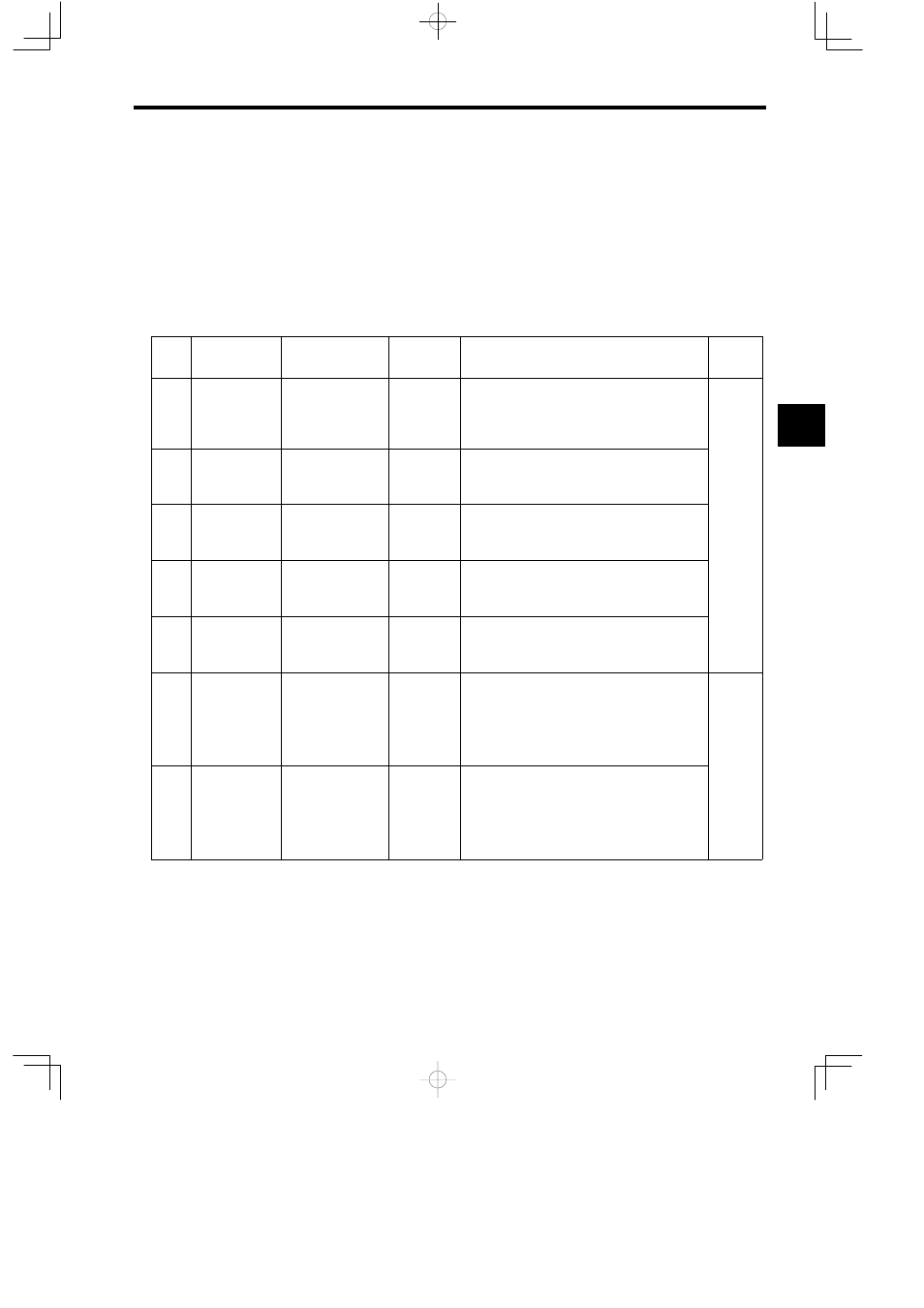
Table 3.14 Types of Drawing Register
Type
Name
Designation
Method
Range
Description
Charac-
teristic
S
System registers
SB, SW, SL,
SFnnnnn (SAnnnnn)
SW00000 to
SW01023
System registers provided by the system. Register
number nnnnn is expressed as a decimal number.
When the system is started, SW00000 to SW00049
are cleared to 0.
Common
to all
drawings
M
Data registers
MB, MW, ML,
MFnnnnn
(MAnnnnn)
MW00000 to
MW32767
Data registers are shared by all drawings. Used as
interfaces between drawings. Register number
nnnnn is expressed as a decimal number.
I
Input registers
IB, IW, IL, IFhhhh
(IAhhhh)
IW0000 to
IW07FF
Registers used for input data.
Register number hhhh is expressed as a hexadecimal
number.
O
Output registers
OB, OW, OL,
Ofhhhh (OAhhhh)
OW0000 to
OW07FF
Registers used for output data.
Register number hhhh is expressed as a hexadecimal
number.
C
Constantregisters CB, CW, CL,
CFnnnnn (CAnnnnn)
CW00000 to
CW04095
Constant registers can be referenced only in the pro-
gram. Register number nnnnn is expressed as a deci-
mal number.
#
# registers
#B, #W, #L,
#Fnnnnn (#Annnnn)
#W00000 to
#W16383
# registers can be referenced only in the program and
can be used only in the corresponding drawing.
The actual range used is specified by the user on the
CP-717. Register number nnnnn is expressed as a
decimal number.
Unique to
each
drawing
D
D registers
DB, DW, DL,
DFnnnnn
(DAnnnnn)
DW00000 to
DW16383
D registers are unique to each drawing and can be
used only in the corresponding drawing.
The actual range used is specified by the user on the
CP-717. Register number nnnnn is expressed as a
decimal number.
Note The servo parameter register number (input or output register number) depends on the axis number (axes 1 to
14). Table 3.15 shows the servo parameter register numbers for each axis.
3