2 i/o unit, Ji/o and status indicators, Jmechatrolink connector – Yaskawa MP930 User Manual
Page 108: Ji/o signal connectors
System Startup
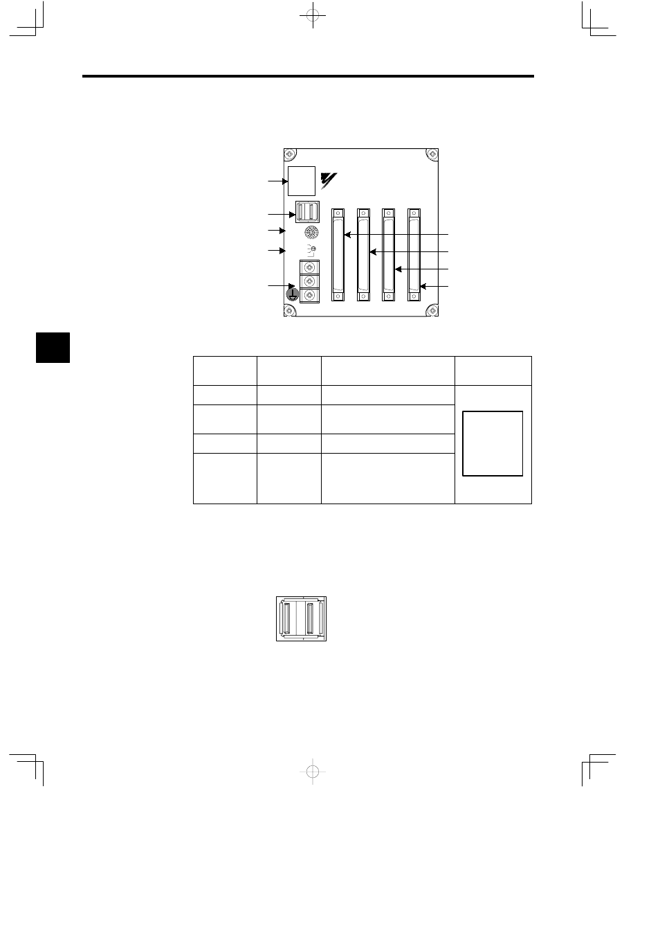
4.1.2 I/O Unit
4 -6
4.1.2 I/O Unit
CN1
IN1
OUT1
IN2
OUT2
A1
A1
A1
A1
B1
B1
B1
B1
YASKAWA
JEPMC−IO350
SW1
SW2 IN1
IN2
OUT1
OUT2
DC24V
DC 0V
I/O indicators
MECHATROLINK connector
Station No. switch
I/O indicator switch
Power terminals
Input signal connector
Input signal connector
Output signal connector
Output signal connector
J
I/O and Status Indicators
Indicator
Name
Indicator Color
Meaning
When Indicator Is Lit
Appearance
R
Green
Lights when current is conducted.
ACTIVE
Orange
Lights during MECHATROLINK
transmission.
R ACTIVE F
1 9
17 25
2 10 18 26
F
Red
Broken fuse
2 10 18 26
3 11 19 27
4 12 20 28
5 13 21 29
1 to 32
Orange
Input signal and output signal moni-
tors.
The indicator meaning is changed with
the I/O indicator switch.
5 13 21 29
6 14 22 30
7 15 23 31
8 16 24 32
J
MECHATROLINK Connector
The MC Unit and Servopack are connected by MECHATROLINK Cable (such as JEPMC-
W6000-A3 or JEPMC-W6000-01).
For details on the connection methods, see 4.3.5 Connecting the Devices.
CN1
J
I/O Signal Connectors
The I/O Unit and external I/O signals are connected by I/O Cables (JEPMC-W5410-05).
Number of signal points: 16 inputs and 16 outputs
4