2 ladder logic programs – Yaskawa MP930 User Manual
Page 18
MP930
1.2.2 Ladder Logic Programs
1 -6
1.2.2 Ladder Logic Programs
A ladder logic program is a program used for coding the sequence logic for conditional control
and sequence control, and for coding the sequence logic that starts an MC program. The ladder
logic program is created as the basic unit called drawings (DWGs).
J
Types of Drawing
The following types of drawing are provided: Start drawing, high-speed scan drawings, low-
speed scan drawings, and user functions.
D
Startup Drawings
Startup drawings are executed once when the power is turned ON. The logic used to set
constants and initialize operation is normally coded in these drawings.
D
High-speed Scan Drawings
High-speed scan drawings are executed at regular intervals. The scan time is within the
range of 2 to 32 ms, and scan times can be set at 2-ms intervals. The circuits used to start
the MC program are coded in the high-speed scan drawings.
D
Low-speed Scan Drawings
Low-speed scan drawings are executed at regular intervals. The scan time is within the
range of 2 to 300 ms, and scan times can be set at 2-ms intervals. Sequence logic that does
not require high-speed processing, such as lamp output and display circuits, should be
coded in low-speed scan drawings.
D
User Functions
User functions are defined as user commands in the coded drawings, using the commands
provided for the MP930. User functions can be used in startup drawings, high-speed scan
drawings, and low-speed scan drawings.
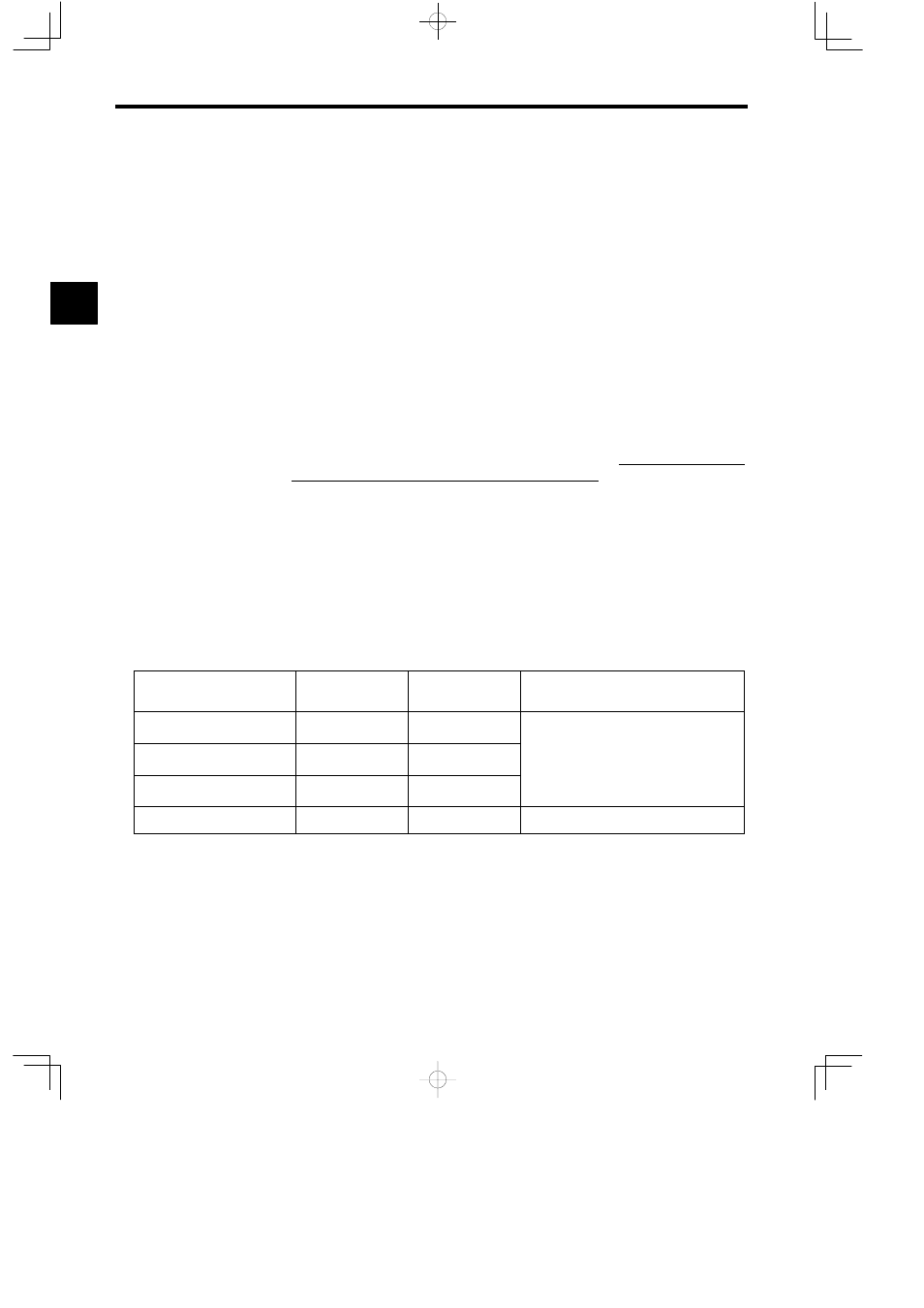
Types of Drawing
Maximum Number
of Drawings
Drawing and
Function Notation
Remarks
Startup Drawings
64
DWG.A
S
500 steps max. per drawing
S
Equivalent to 20 Ksteps max of ladder log-
High-speed Scan Drawings
100
DWG.H
S
Equivalent to 20 Ksteps max. of ladder log-
ic program memory
S
Security function can be set separately for
Low-speed Scan Drawings
100
DWG.L
S
Security function can be set separately for
each drawing.
User Functions
200
FUNC-xxx
S
Separate revision history or each drawing.
1