Jconnections to the sgdb- jj an servopack – Yaskawa MP930 User Manual
Page 125
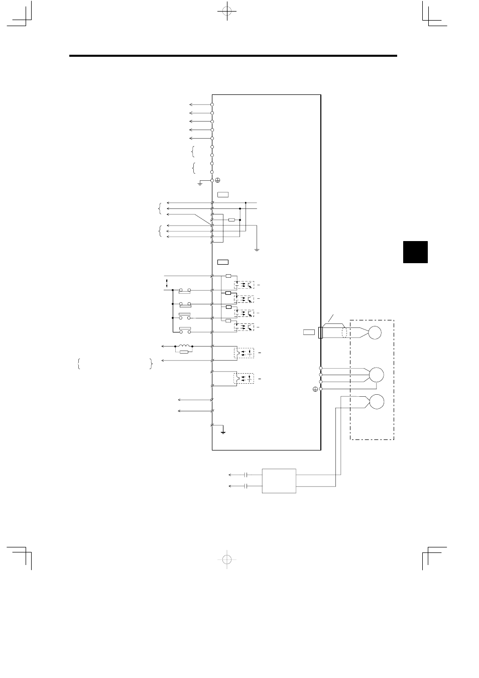
4.2 Connection Methods
4 -23
J
Connections to the SGDB-jjAN Servopack
CN1
P1
B
N
Forward drive prohibited
Servopack
SGDB-jjAN
Connector shell
+24 V
+24 V
3.3 KΩ
Forward drive prohibit limit switch
Reverse drive prohibit limit switch
Zero point return deceleration limit
switch
Current position external latch/zero
N−LS
P−OT
6
7
N−OT
P−LS
DEC−LS
/DEC
/EXT
LATCH−LS
Reverse drive prohibited
Zero point return
deceleration limit
Current position latch
signals
For absolute encoder
Backup battery *4
(To battery module)
BAT(−)
BAT(+)
15
14
BRK
+24 V
0 V
CN2
PG
W
V
U
Be sure to connect the
shield wire at the end Unit.
Optical
encoder
BR
Brake
BR
K
100 VAC
200 VAC
P
8
9
10
1
2
3
4
BRK
SG−BRK
ALM
SG−ALM
BAT
0⋅BAT
R1
T1
MECHATROLINK 1
MECHATROLINK 2
T
r
t
R
S
S1
r
t
Do not connect.
For regenerative resistance connection
*1
Brake control output
Alarm output
*2
Brake control relay
Photocoupler output
Maximum operational voltage: 30 VDC
Maximum output current: 50 mA DC
CN3
1
2
3
4
5
6
7
8
*3
* 1. There is no P1 terminal for a Servopack with a
capacity of less than 5 kW.
* 2. Fordetails on MECHATROLINKconnections,
see 4.2.4.
* 3. When a brake built into the motor or an exter-
nal brake is used, a BRK signal is received by
the relay and controls the brake.
* 4. Connectedwhenanabsoluteencoderisused.
* 5. For Zero point return methods 1 and 2, con-
nect ZERO signal (Zero point LS) to /EXT sig-
nal.
Brake
power
supply
M
Motor
The shielded wire is connected
to the connector shell.
*5
4