Yaskawa MP930 User Manual
Page 84
3.5 Functions
3 -25
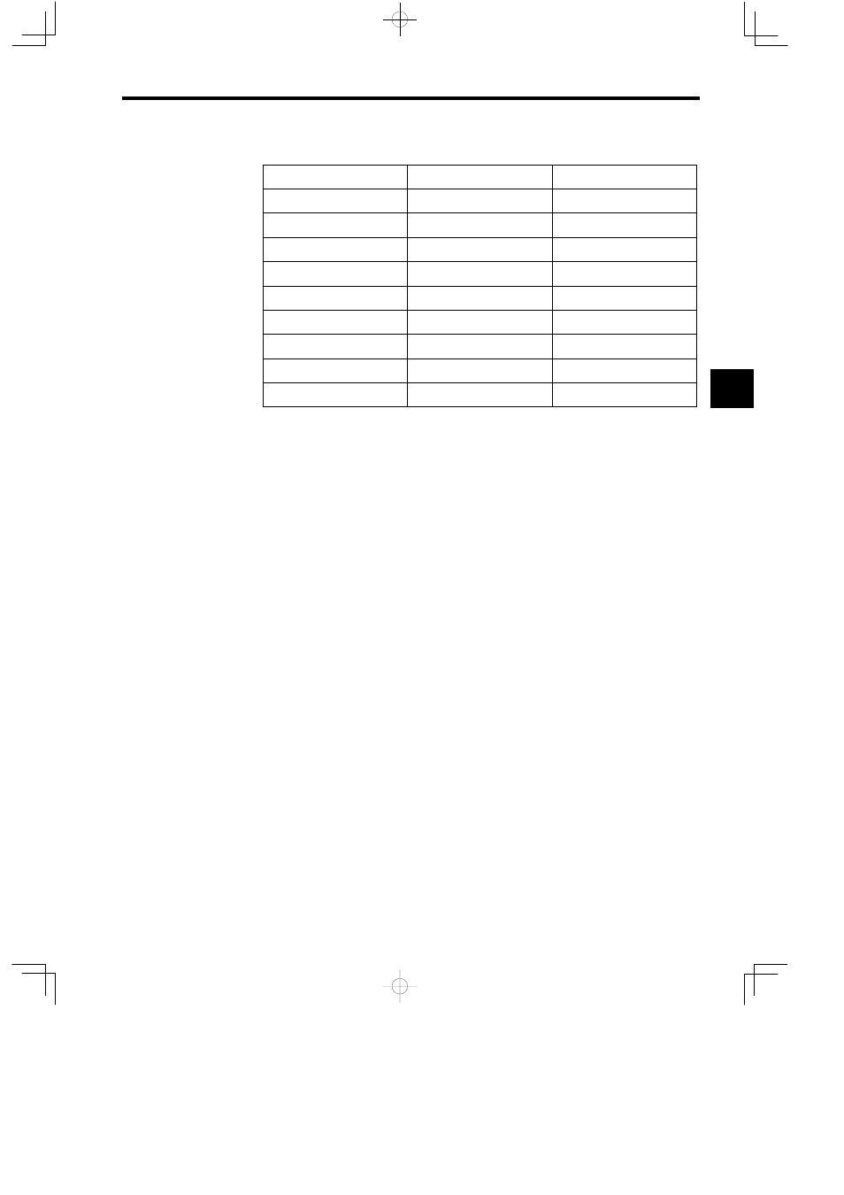
Table 3.10 Allocation of I/O Registers
Name
Data Type
I/O Register
IN_01 (BIT1)
Bit
XB000000
IN_02 (BIT2)
Bit
XB000001
IN_03 (FLT1)
Real number
XF00001
IN_04 (INT1)
Integer
XW00003
IN_05 (ADR)
Address input
AW00000
OUT_01 (BIT3)
Bit
YB000000
OUT_02 (BIT4)
Bit
YB000001
OUT_03 (LNG1)
Double integer
YL00001
OUT_04 (INT2)
Integer
YW00003
Note XW00000 and YW00000 of the X and Y registers are used for bit data.
The function I/O registers shown in Figure 3.13 are allocated automatically. The external
framework of the function is completed at this stage.
J
Creating the Body of the Function
The body of the function is created in the same way as the drawings except that the types of
register used are different. For details on the registers, see 3.6.3 Types of Register.
J
Creating the Program that Calls the Function
The user function is completed when the graphic representation and body program of the func-
tion have been created. As with the standard system functions, user functions can be called
from any parent, child, or grandchild drawing or any other user function.
Functions can be called from a drawing or from within the program of another user function
by using the following procedure. For details on the operation methods, refer to the MP9jj
Machine Controller Programming Software User’s Manuals (SIEZ-C887-2.2-1, SIEZ-
C887-2.2-2) .
1. Input the function name using the FSTART instruction.
Example: Input “FSTART, Enter Key, TEST, Enter Key”.
The previously defined graphic representation of the function will be displayed.
2. Use the FIN instruction to create the input data program.
Provide input data for the function inputs and address inputs.
3. Use the FOUT instruction to create the output data program.
3