Yaskawa MP930 User Manual
Page 195
Parameters
5.1.2 Parameter Lists
5 -10
Do not normally use the electronic gear ratio parameters on the Servopack, but set the Cn-0024 and Cn-0025
to 1 during set up. When the electronic gear ratio on Servopack is 1:1, the reference unit on the Servopack is
in pulse.
J
Memory Switch Bit Details
The following describes individual memory switch bits (bit user constants) from the list of Ser-
vopack user constants.
Cn-001: Memory Switches 1
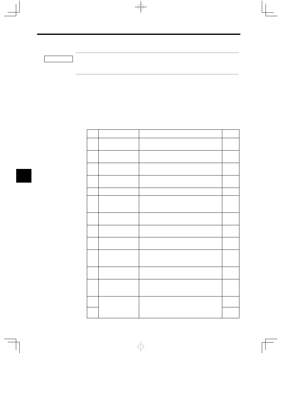
Cn-001: The following table describes the bits in memory switches 1.
Bit
Name
Description
Default
0
SV_ON mask
0: SV_ON/SV_OFF enabled
1: Always SV_ON
0
1
SENS_ON mask
0: SENS_ON/SENS_OFF enabled
1: Always SENS_ON
0
2
P-OT mask
0: P-OT enabled
1: P-OT signal mask (Always disabled)
0
3
N-OT mask
0: N-OT enabled
1: N-OT signal mask (Always disabled)
0
4
−
0
5
Power outage mask
0: Servo alarm after recovery from power outage
1: Power outage mask (No servo alarm with power
outage recovery)
0
6
Base block power outage
prevention method
0: Dynamic brake (DB) stop
1: Free run stop
0
7
Status after dynamic
brake stop
0: Cancel dynamic brake
1: Do not cancel dynamic brake
1
8
Operation with OT stop
0: Stop according to bit 6 setting
1: Decelerate to a stop using emergency stop torque
1
9
Operation after decelerat-
ing to a stop using OT
emergency stop torque
0: Servo OFF after decelerating to a stop
1: Zero clamp after decelerating to a stop
1
A
Position error with servo
OFF
0: Clear position error
1: Hold position error
0
B
Mode switch function
0: Mode switch function enabled (according to bits C
and D)
1: Mode switch function disabled
0
C
Mode switch selection
00: Mode switch selection: Internal torque reference
01: None (Do not use this setting.)
0
D
(
g )
10: Mode switch selection: Acceleration
11: Mode switch selection: Error pulse
0
5
IMPORTANT