Control panel buttons, Operation – Grass Valley CRSC v.3.2 User Manual
Page 154
142
Operation
Control Panel Buttons
Control Panel Buttons
All CR Series control panels have common button features. The CQX panels are somewhat
different and operate on their own network. See
Most CR Series control panels were designed before the existence of the Compact Router
System Configurator (CRSC). Their button layouts (and button colors) are appropriate to what
has been called “default” mode (and what this document calls “stand-alone” mode) where green
buttons are grouped together and labeled “Source” and amber buttons are grouped together
and labeled “Dest.” For these earlier panels, this coloring has little meaning in a CRSC network.
On these early panels, the labels “Source” and “Dest” at the left have no meaning in a CRSC
network. Operators must ignore these colors and these labels.
The newer CP6464, a 64×64 panel, does not suffer from the fixed coloring of the earlier panels.
Any button can be green or amber, depending on its function.
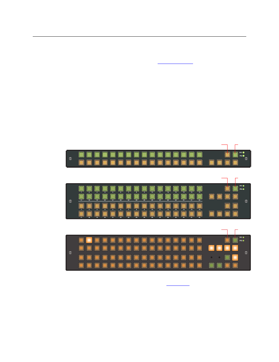
Figures B-1, B-2, and B-3 show the CP1616, CP3232, and CP6464 respectively. Other panel types
are variations of these. The CP1604 for instance has only 4 buttons in the lower row. The CP6401
(a configuration variant of the CP6464) does not have any destination buttons.
Fig. B-1: CP1616
Fig. B-2: CP3232
Fig. B-3: CP6464
The color red indicates one of several conditions. See
, following. A button that is
unlit is either (1) undefined or (2) momentarily turned off.
There are two fixed-function buttons on all control panels (CQX included) at the top right, as
shown in Figures B-1, B-2, and B-3.
Source
Dest
1
2
3
4
5
6
7
8
9
10
11
12
13
14
15
16
Panel Lock
Destination Lock
Source
Dest
Panel Lock
Destination Lock
Panel Lock
Destination Lock
49 50
51 52 53 54 55 56 57
58 59 60 61
62
63
64
33 34 35
36
37
38 39 40
41 42 43
44
45 46 47 48
17 18 19 20 21
22 23 24
25 26
27 28 29 30
31
32
1
2
3
4
5
6
7
8
9
10
11
12
13
14
15
16