Page features – Grass Valley CRSC v.3.2 User Manual
Page 116
104
NV9000 Remote Panel Settings Page
Summary
Page Features
In the middle of the page is ‘Network Frame Summary’ in which there are 3 tabbed pages. Use
the ‘Remote Panels’ tab to select a remote panel module (by clicking a radio button). The other
two tabs are for information only.
At the top of the page is a check box with which you enable or disable NV9000 mode for the
selected remote panel module. Associated with the check box is a field in which you can specify
the unit’s panel ID (required in NV9000 systems) and another check box in which you can specify
whether the panel will have a fixed IP address or whether the NV9000 system will use DHCP
1
to
determine its IP address.
At the bottom of the page is a ‘Refresh Summary’ button. Click this button at any time to be sure
that you are viewing the most current information.
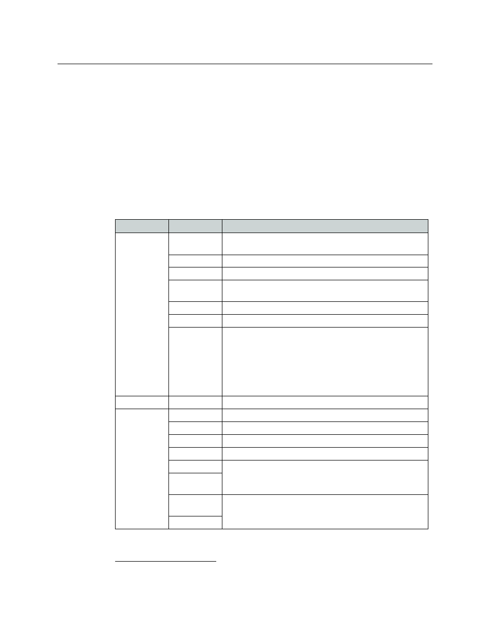
The ‘Network Frame Summary’ presents the following option and information:
1.
Dynamic Host Configuration Protocol
Tab
Column
Description
Remote Panels
Edit/Update
Click the radio button on the row displaying the remote panel mod-
ule you want to convert.
Name
Name of the remote panel module.
Frame Type
Type of remote panel module by model number.
Panel Type
Type of control panel by model number. If the type is unknown, the
entry will read “unknown.”
Panel Mode
Either standard, enhanced with hold, or enhanced without hold
IP Address
IP address currently assigned to the device.
Identify CP
When you click Identify CP, the control panel mounted on the
remote panel module listed on that row identifies itself by display-
ing a moving pattern of button lights.
This feature is helpful if you forget which panel of possibly many is
represented by the particular IP address.
The moving button lights continue indefinitely. To turn off the pat-
tern, click any button on the panel or click Identify CP again.
Levels
Level
The name and number assigned to the level.
Signal Type
The signal type of the router to which the level is assigned.
Router
Router to which the level is assigned.
Frame Type
Type (model number) of the router to which the level is assigned.
Router IP
IP address assigned to the router.
Physical Inputs
The physical start and end points of the level within the router.
Physical Out-
puts
Controller
Sources
I/O numbering in a remote panel might not match the physical I/O
numbers of the router. Use these fields to map the router’s number-
ing to the NV9000’s numbering.
Controller Dests