Analog video routers – Grass Valley CRSC v.3.2 User Manual
Page 144
132
Tutorials
Products
Customers should have no reason to remove the fan unit.
The CQX video routers have a “mode” switch in addition to the 16-position frame ID switch. Both
are 16-position rotary switches that turn with a small screwdriver. The “mode” switch configures
the video format of the router.
Set the rotary switch to a position in the range 0–9, A, B, C, or D, according to this table:
The default is 1080i, 59.94 Hz (switch setting 0). Positions E and F are not valid positions.
Where a switch setting supports multiple formats, the format is governed by the video reference
applied to the router and must be compatible with that reference format.
The CQX routers enter non-sync bypass mode for signals at all other rates.
Every time you make a switch change, power-cycle the router.
Settings 6 and 7 are for SMPTE 425 level A. Settings 8 and 9 are for SMPTE 425 level B.
Analog Video Routers
The 1RU analog video routers have 16×16, 16×4, or 8×8 crosspoints. The 2RU analog video
routers have either 32×32 or 32×4 crosspoints.
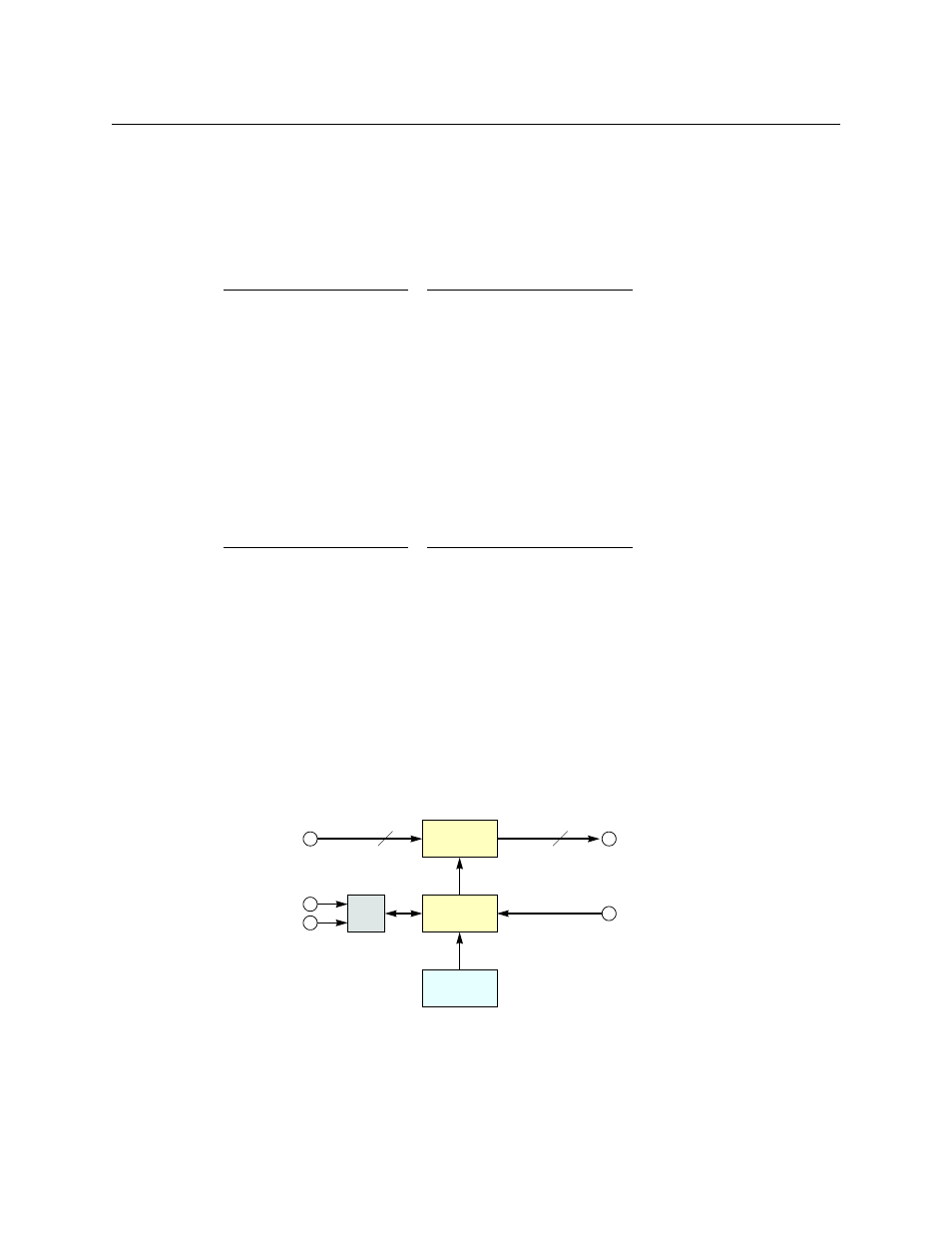
Figure A-23 shows a simplified view of an analog video router:
Fig. A-23: Block Diagram of the Analog Video Router
The analog video routers switch NTSC (525i) or PAL (625i) video signals. The router outputs are
switched in sync with an external video reference if it is present.
Setting Format
Setting Format
0
1080i, 59.94 or 60
1080p, 29.97 or 30
1080psf, 29.97 or 30
6
1080p, 59.94 or 60
Switch positions 6 and 7
correspond to video accord-
ing to SMPTE 425 level A.
Switch positions 8 and 9
correspond to video accord-
ing to SMPTE 425 level B.
7
1080p, 50
8
2 × 1080i, 59.94 or 60
1
1080i, 50
1080p, 25
1080psf, 25
9
2 × 1080i, 50
A
720p, 29.97 or 30
B
720p, 25
2
525i, 59.94
C
720p, 23.98 or 24
3
625i, 50
D
1080p, 23.98 or 24,
1080psf, 23.98 or 24
4
720p, 59.94 or 60
5
720p, 50
E
reserved
F
reserved
M
N
μP
Logic
Inputs
Outputs
Crosspoint
Switch
Control
Panel
Video Refer-
ence
Automation
Ethernet
(optional)
M = 8, 16 or 32
N = 4, 8, 16, or 32