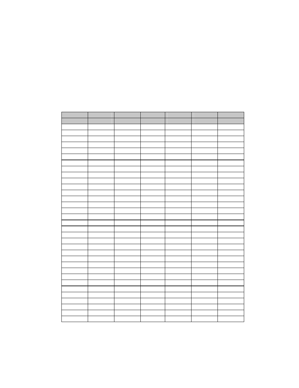
Table 7-1. conversion to s/n and eb/no chart – Comtech EF Data CIM-300L User Manual
Page 140

CiM-300L IP Enabled Satellite Modem
Rev. 1
System Checkout/Fault Isolation CD/CIM300L.IOM
114
a
Set the modem to the continuous wave Normal mode by using the Carrier Mode front
panel menu. This sets the Carrier mode in the off condition. A pure carrier should now
be present at the IF output. This should only be used for frequency measurements. In
this mode, spurious and power measurements will be inaccurate.
b
Set the modem to the continuous wave Offset mode by using the Carrier Mode front
panel menu. This generates a single, upper side-band-suppressed carrier signal.
Ensure the carrier and side-band suppression is < -35 dBc.
Table 7-1. Conversion to S/N and Eb/No Chart
(dB)
Code
Rate 1/2
Code
Rate 3/4
Code
Rate 7/8
(S+N)/N
S/N
Eb/No
S/N
Eb/No
S/N
Eb/No
4.0 1.8 1.8 1.8 0.0 1.8 -0.6
4.5 2.6 2.6 2.6 0.8 2.6 0.2
5.0 3.3 3.3 3.3 1.6 3.3 0.9
5.5 4.1 4.1 4.1 2.3 4.1 1.6
6.0 4.7 4.7 4.7 3.0 4.7 2.3
6.5 5.4 5.4 5.4 3.6 5.4 3.0
7.0 6.0 6.0 6.0 4.3 6.0 3.6
7.5 6.6 6.6 6.6 4.9 6.6 4.2
8.0 7.3 7.3 7.3 5.5 7.3 4.8
8.5 7.8 7.8 7.8 6.1 7.8 5.4
9.0 8.4 8.4 8.4 6.7 8.4 6.0
9.5 9.0 9.0 9.0 7.2 9.0 6.6
10.0 9.5 9.5 9.5 7.8 9.5 7.1
10.5 10.1 10.1 10.1 8.3 10.1 7.7
11.0 10.6 10.6 10.6 8.9 10.6 8.2
11.5 11.2 11.2 11.2 9.4 11.2 8.8
12.0 11.7 11.7 11.7 10.0 11.7 9.3
12.5 12.2 12.2 12.2 10.5 12.2 9.8
13.0 12.8 12.8 12.8 11.0 12.8 10.3
13.5 13.3 13.3 13.3 11.5 13.3 10.9
14.0 13.8 13.8 13.8 12.1 13.8 11.4
14.5 14.3 14.3 14.3 12.6 14.3 11.9
15.0 14.9 14.9 14.9 13.1 14.9 12.4
15.5 15.4 15.4 15.4 13.6 15.4 12.9
16.0 15.9 15.9 15.9 14.1 15.9 13.5
16.5 16.4 16.4 16.4 14.6 16.4 14.0
17.0 16.9 16.9 16.9 15.2 16.9 14.5
17.5 17.4 17.4 17.4 15.7 17.4 15.0
18.0 17.9 17.9 17.9 16.2 17.9 15.5
18.5 18.4 18.4 18.4 16.7 18.4 16.0
19.0 18.9 18.9 18.9 17.2 18.9 16.5
19.5 19.5 19.5 19.5 17.7 19.5 17.0
20.0 20.0 20.0 20.0 18.2 20.0 17.5
