Figure 79. flash loader processor dialog box – Zilog Z8F0130 User Manual
Page 150
Using the Integrated Development Environment
UM013037-1212
126
Zilog Developer Studio II – Z8 Encore!
User Manual
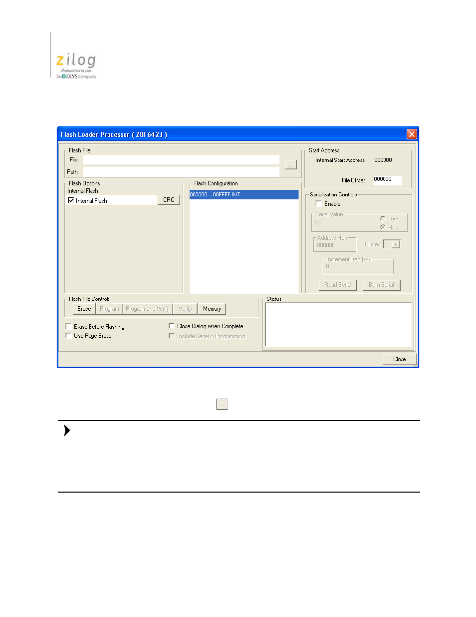
3. Click the
Browse
button (
) to navigate to the hex file to be flashed.
The Flash Loader is unable to identify, erase, or write to a page of Flash that is protected
through hardware.
For example, a target might have a write enable jumper to protect the boot block. In this
case, the write enable jumper must be set before flashing the area of Flash. The Flash
Loader displays this page as disabled.
4. Select the
Internal Flash
checkbox in the
Flash Options
area.
The internal Flash memory configuration is defined in the
CpuFlashDevice.xml
file. The device is the currently selected microcontroller or microprocessor. When the
Figure 79. Flash Loader Processor Dialog Box
Note:
- Z8F0131 Z8F0230 Z8F0231 Z8F0430 Z8F0431 Z8F043A Z8F0830 Z8F0831 Z8F083A Z8F1232 Z8F1233 Z8F0113 Z8F011A Z8F0123 Z8F012A Z8F0213 Z8F021A Z8F0223 Z8F022A Z8F0411 Z8F0412 Z8F0413 Z8F041A Z8F0421 Z8F0422 Z8F0423 Z8F042A Z8F0811 Z8F0812 Z8F0813 Z8F081A Z8F0821 Z8F0822 Z8F0823 Z8F082A Z8F0880 Z8F1621 Z8F1622 Z8F1680 Z8F1681 Z8F1682 Z8F2421 Z8F2422 Z8F2480 Z8F3221 Z8F3222 Z8F3281 Z8F3282 Z8F4821 Z8F4822 Z8F4823 Z8F6081 Z8F6082 Z8F6421 Z8F6422 Z8F6423 Z8F6481 Z8F6482 Z8FS021A ZMOT1AHH Z8FS040B ZMOT0BHH ZMOT0BSB Z8FMC04 Z8FMC08 Z8FMC16