68 2. set-up and connection – Leica Geosystems GPS System 500 - Technical Reference Manual User Manual
Page 68
68
2. Set-up and Connection
Technical Reference Manual-4.0.0en
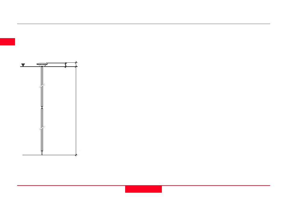
3. Pole Setup
VO = 0
VR
MRP
VE
1
VE
2
VO
Vertical Offset
VR
Vertical Height Reading
VE1
Vertical Phase Center Eccentricity for L1.
VE2
Vertical Phase Center Eccentricity for L2
MRP Mechanical Reference Plane
Although an AT501/502 Antenna is shown, the same principles apply to the
AT504 and AT303.
The Vertical Height Reading (VR) value fixed at the height of the pole. With a
standard Leica System 500 pole this is 2.0m. There are two System 500 upper
pole halves. One has a 5/8 inch screw - the Antenna screws on directly. The
other has a stub and uses a GAD31 stub to screw adapter. Whichever pole
type is used, the height remains at 2.00m. Additional 1.00 m pole sections
maybe easily added or subtracted. In some special cases where the lower half
of the pole alone is used, the height will be 1.00m.
The Vertical Offset (VO) value is zero in this case.
The Vertical Phase Center Eccentricities are stored in the Receiver for all
Leica System 500 Antennas and any non-Leica Antenna that you define. As
long as the correct Antenna is chosen there is no need to enter any value into
the Receiver. These values do need to be calculated when a new type of
Antenna that does not exist in the Antenna Setup Records is used.