Leica Geosystems GPS System 500 - Technical Reference Manual User Manual
Page 228
228
7. Measuring with System 500
Technical Reference Manual-4.0.0en
Station Inc - The distance between
each grid point in the direction of the
Reference Line.
Scale - Depending on the
transformation method used and the
stake out design criteria, you may
specify a scale factor to be applied to
the increment value within the map
projection plane. This is only used
when staking out grids over large
areas (tens of kilometers) and
otherwise should be left at the default
value of 1.00.
Refer to the diagrams at the start of
this section for more details of each
parameter.
Press CONT (F1) to continue.
The first point in the grid is
automatically selected as the target
point and measurements to that point
are given.
Information about the point you are
looking for is given in the Directory
Bar.
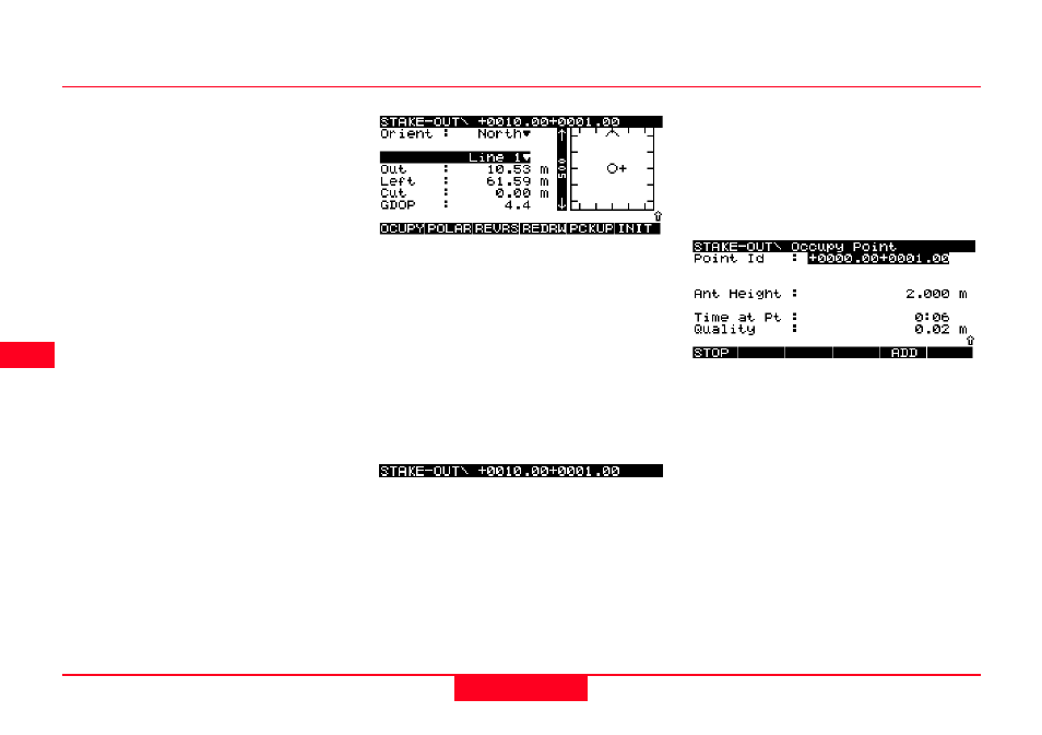
The point is given as:
+XXXX.XX+YYYY.YY
Where
X is the distance along the Refer-
ence Line.
Y is the Horizontal Offset from the
Reference Line.
Move to the point and record/stake it.
Press OCUPY (F1).
The Point Id is automatically chosen
according to the format explained
previously.
Alternatively, you may press SHIFT
and then PT ID (F3) to toggle be-
tween using the Point ID currently
defined in the Occupy template and
the suggested Line Id as described in
section 7.5.13.