Rockwell Automation 1734-AENTR EtherNet/IP Network Configuration User Manual User Manual
Page 95
Rockwell Automation Publication ENET-UM001L-EN-P - March 2014
95
Send Email Chapter 7
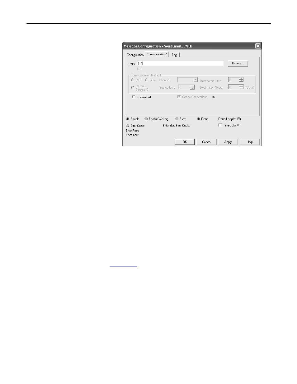
3. Click the Communication tab.
4. In the Path field, type the path from the controller to the EtherNet/IP
communication module.
The path starts with the controller initiating the MSG instruction. The
second number in the path represents the port from which the message
exits and the address of the next module in the path.
For example, if the EtherNet/IP communication module is in the same
chassis as the controller and is in slot 2, the path is: 1, 2.
5. If all the devices in the path are configured in the initiating controller’s I/O
Configuration tree, click Browse to select the target module.
The software automatically fills in the path.
6. Click OK.
RM003
.
This manual is related to the following products:
- 1734-AENT EtherNet/IP Network Configuration User Manual 22-COMM-E EtherNet/IP Network Configuration User Manual 20-COMM-E EtherNet/IP Network Configuration User Manual 1794-AENT EtherNet/IP Network Configuration User Manual 1783-Etxx EtherNet/IP Network Configuration User Manual 1769-Lxxx EtherNet/IP Network Configuration User Manual 1756-Enxx EtherNet/IP Network Configuration User Manual