Connect a cerabar s pressure transmitter – Rockwell Automation 1734sc-IE4CH E+H Instruments via HART to PlantPAx User Manual User Manual
Page 122
122
Rockwell Automation Publication PROCES-UM002A-EN-P - July 2014
Appendix H
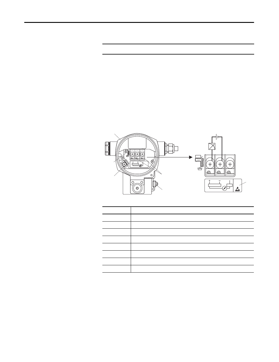
Cerabar S Pressure Transmitter
Connect a Cerabar S Pressure
Transmitter
Use a 2-wire connection to the HART input module.
1. Switch off the supply voltage before connecting the device.
2. Remove housing cover of the terminal compartment.
3. Guide cable through the gland. Preferably use twisted, screened two-wire
cable.
4. Connect device in accordance with the following diagram.
5. Screw down housing cover.
6. Switch on supply voltage.
IMPORTANT
The supply voltage must match the supply voltage on the nameplate.
Item
Description
1
Housing
2
Jumper for 4...20 mA test signal
3
Internal earth terminal
4
External earth terminal
5
4...20 mA test signal between plus and test terminal
6
Minimum supply voltage = 10.5 V DC, jumper is inserted in accordance with the illustration
7
Minimum supply voltage = 11.5 V DC, jumper is inserted in “Test” position
8
Devices with integrated overvoltage protection are labeled OVP (overvoltage protection) here
4…20 mA
➅
10.5 V DC
➆
11.5 V DC
4... 20mA
Test
Test
➀
➁
➂
➃
➄
Test
➇
4... 20mA
Test
- 1734sc-IE2CH E+H Instruments via HART to PlantPAx User Manual 1769sc-IF4IH E+H Instruments via HART to PlantPAx User Manual 1794-IF8IH E+H Instruments via HART to PlantPAx User Manual 1756-IF16H E+H Instruments via HART to PlantPAx User Manual 1756-IF8IH E+H Instruments via HART to PlantPAx User Manual 1756-IF8H E+H Instruments via HART to PlantPAx User Manual