Wiring chapter 8, Table 8.h resolver connector/cable information, Figure 8.8 resolver wiring – Rockwell Automation 8510 AC Spindle Drive System User Manual User Manual
Page 91: For: 1327ab series a motor, Mate-n-lok pin orientation for, Dynamic connector pin orientation
Wiring
Chapter 8
8-87
A pin extraction tool (AMP # 914677-1) is required to remove a pin from
the housing. Both items are available from Allen-Bradley as part of the
8510SA-CTA crimp tool kit.
As previously described, three termination options are available for the
CN3 connector: l) a mating connector kit, 2) a termination panel, and 3) an
interface cable assembly. The following table shows the I/O function
assignment for each of these termination options.
Table 8.H
Resolver Connector/Cable information
Honda
Connector
Pin Num-
ber
14
8
1
15
9
2
17
11
3
20
13
4
Signal
Description
Stator – S1
Stator – S3
Pair Shield
Stator – S2
Stator – S4
Pair Shield
Rotor – R1
Rotor – R2
Pair Shield
Thermal Switch
Thermal Switch
Overall Shield
Cable
Assembly
Wire Color
and (Pair #)
Red (1)
Black (1)
Shield (1)
White (2)
Black (2)
Shield (2)
Green (3)
Black (3)
Shield (3)
Blue (4)
Black (4)
Braid Shield
Termina-
tion
Panel
Terminal
Number
14
8
1
15
9
2
17
11
3
20
13
4
Connector
Pin Number for
1327AB Series
A
1
3
2
5
7
6
9
11
10
15
16
12
Connector
Pin Number for
1327AD Series
A
1
2
Cut
3
4
Cut
5
6
Cut
9
10
7
Connector Pin
Number for 1327AB
Series B,
1327AC Series A,
1327AD Series B
B1
A1
Cut
B2
A2
Cut
B3
A3
Cut
B5
A5
B4
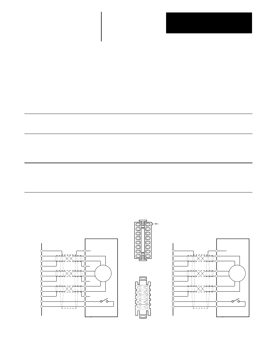
See Figure 8.8 for typical resolver interconnect wiring.
Figure 8.8
Resolver Wiring
CN3-4
FG4
CN3-14
S1
CN3-8
S3
CN3-15
CN3-9
CN3-2
S2
S4
FG2
CN3-17
CN3-11
CN3-3
R1
R2
FG3
CN3-20
0L
CN3-13
ISO-SG
CN3-1
FG1
Resolver
1
3
2
7
6
9
11
10
15 (T1)
16 (T2)
5
12
for: 1327AB Series A Motor
CN3-4
FG4
CN3-14
S1
CN3-8
S3
CN3-15
CN3-9
CN3-2
S2
S4
FG2
CN3-17
CN3-11
CN3-3
R1
R2
FG3
CN3-20
0L
CN3-13
ISO-SG
CN3-1
FG1
Resolver
B1 (1)
A1 (2)
A2 (4)
B3 (5)
A3 (6)
B5 (9)
A5 (10)
B2 (3)
T1
T2
B4 (7)
1327AB Series B Motor
1327AC Series A Motor
1327AD Series (A) & B Motor
Pin 1
Indicator
3
2
4
6
8
10
12
14
16
5
7
9
11
13
15
MATE-N-LOK
Pin Orientation
for:
Important: Pin designations for 1326AD Series A Motors
are shown in (parenthesis).
A1
A2
A3
A4
A5
B2
B3
B4
B5
Dynamic Connector
Pin Orientation
B
A
B1
Note: See end of connector for A/B
labels, numbers are labeled on side.