Flange mount motor, Dimensions chapter 3, Dimensions are in millimeters) – Rockwell Automation 8510 AC Spindle Drive System User Manual User Manual
Page 30
Dimensions
Chapter 3
3-26
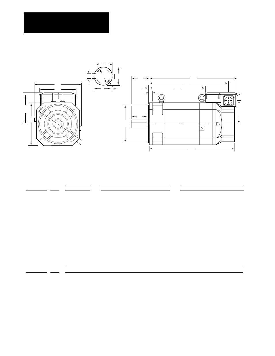
Figure 3.9
1327AB and 1327AD Series A Flange Mount Motor
ES
AK
BE
BB
XM
XC
XN
AH
AC
XL
P
AB
BH
4 -
∅
BF
AJ
1327AB-AFM-02-F
1327AB-AFM-04-F
1327AB-AFM-06-F
1327AB-AFL-08-F
1327AB-AFL-11-F
1327AB-AFL-15-F
1327AB-AFL-19-F
1327AB-AFL-22-F
1327AD-ABL-04-F
1327AD-ABL-06-F
1327AD-ACL-08-F
1327AD-AAK-11-F
1327AD-AAK-15-F
1327AD-AAK-19-F
Catalog Number
174
214
214
270
270
250
250
250
250
250
250
330
384
384
P
359
407
447
418
458
508
560
600
453
491
539
687
666
716
AG
174
204
204
250
250
250
250
250
250
250
250
310
380
380
BH
35
51
51
51
51
51
63
63
49
49
49
61
61
61
AA
149
178
178
202
202
207
207
207
183
183
183
212
280
280
AB
106
126
126
150
150
152
152
152
131
131
131
158
216
216
AC
343
376
416
383
423
496.5
546.5
586.5
398
436
484
667
628
678
XC
194
214
214
214
214
241
241
241
320
320
320
330
385
385
XL
385
425
465
433
473
551
601
641
441
479
527
722
687
737
XN
XM
215
235
275
243
283
331
381
421
265
303
351
491
430
480
Flange Mount Motor
(Dimensions are in millimeters)
∅
AA
AG
1327AB-AFM-02-F
1327AB-AFM-04-F
1327AB-AFM-06-F
1327AB-AFL-08-F
1327AB-AFL-11-F
1327AB-AFL-15-F
1327AB-AFL-19-F
1327AB-AFL-22-F
1327AD-ABL-04-F
1327AD-ABL-06-F
1327AD-ACL-08-F
1327AD-AAK-11-F
1327AD-AAK-15-F
1327AD-AAK-19-F
Catalog Number
28 j6
(+0.009/–0.004)
28 h6
(+0.000/–0.013)
32 h6
(+0.000/–0.016)
48 h6
(+0.000/–0.016)
48 h6
(+0.000/–0.016)
48 h6
(+0.000/–0.016)
55 h6
(+0.000/–0.019)
55 h6
(+0.000/–0.019)
48 h6
(+0.000/–0.016)
48 h6
(+0.000/–0.016)
55 h6
(+0.000/–0.019)
60 h6
(+0.000/–0.019)
70 h6
(+0.000/–0.019)
70 h6
(+0.000/–0.019)
U
60
60
80
110
110
110
110
110
110
110
110
140
140
140
AH
-
49
75
97
97
97
98
98
90
90
90
110
110
110
ES
-
24
(0.0/–0.2)
27
(0.0/–0.2)
42.5
(0.0/–0.2)
42.5
(0.0/–0.2)
42.5
(0.0/–0.2)
49
(0.0/–0.2)
49
(0.0/–0.2)
42.5
(0.0/–0.2)
42.5
(0.0/–0.2)
49
(0.0/–0.2)
53
(0.0/–0.2)
62.5
(0.0/–0.2)
62.5
(0.0/–0.2)
R
-
8 P9
(–0.015/–0.051)
10 P9
(–0.015/–0.051)
14 P9
(–0.018/–0.061)
14 P9
(–0.018/–0.061)
14 P9
(–0.018/–0.061)
16 P9
(–0.018/–0.061)
16 P9
(–0.018/–0.061)
14 P9
(–0.018/–0.061)
14 P9
(–0.018/–0.061)
16 P9
(–0.018/–0.061)
18 P9
(–0.018/–0.061)
20 P9
(–0.022/–0.074)
20 P9
(–0.022/–0.074)
S
185
215
215
265
265
265
265
265
265
265
265
350
400
400
AJ
150 h7
(+0.000/–0.040)
180 h7
(+0.000/–0.040)
180 h7
(+0.000/–0.040)
230 h7
(+0.000/–0.046)
230 h7
(+0.000/–0.046)
230 h7
(+0.000/–0.046)
230 h7
(+0.000/–0.046)
230 h7
(+0.000/–0.046)
230 h7
(+0.000/–0.046)
230 h7
(+0.000/–0.046)
230 h7
(+0.000/–0.046)
300 h7
(+0.000/–0.052)
350 h7
(+0.000/–0.057)
350 h7
(+0.000/–0.057)
AK
Overall
Conduit Box
Shaft and Key
Flange
5
5
5
5
5
5
5
5
5
5
5
5
5
5
BB
15
18
18
20
20
20
20
20
18
18
18
20
22
22
BE
11
15
15
15
15
15
15
15
15
15
15
19
24
24
BF
-
8 h9
(+0.0/–0.036)
10 h9
(+0.0/–0.036)
14 h9
(+0.0/–0.043)
14 h9
(+0.0/–0.043)
14 h9
(+0.0/–0.043)
16 h9
(+0.0/–0.043)
16 h9
(+0.0/–0.043)
14 h9
(+0.0/–0.043)
14 h9
(+0.0/–0.043)
16 h9
(+0.0/–0.043)
18 h9
(+0.0/–0.043)
20 h9
(+0.0/–0.052)
20 h9
(+0.0/–0.052)
Key - W
U
S
R
XA
XB
R
Shaft Detail
-
16
22
38
38
38
45
45
38
38
45
50
60
60
XA
-
2 – M6 x 10 deep
4 – M5 x 10 deep
4 – M5 x 10 deep
4 – M5 x 10 deep
4 – M5 x 10 deep
4 – M5 x 10 deep
4 – M5 x 10 deep
4 – M5 x 10 deep
4 – M5 x 10 deep
4 – M5 x 10 deep
4 – M6 x 10 deep
4 – M6 x 10 deep
4 – M6 x 10 deep
XB
-
7 h11
(+0.0/–0.09)
8 h11
(+0.0/–0.09)
9 h11
(+0.0/–0.09)
9 h11
(+0.0/–0.09)
9 h11
(+0.0/–0.09)
10 h11
(+0.0/–0.09)
10 h11
(+0.0/–0.09)
9 h11
(+0.0/–0.09)
9 h11
(+0.0/–0.09)
10 h11
(+0.0/–0.09)
11 h11
(+0.0/–0.11)
12 h11
(+0.0/–0.11)
12 h11
(+0.0/–0.11)
Key - H
A
A
A
A
A
A
A
A
A
A
A
A
A
A
Series
A
A
A
A
A
A
A
A
A
A
A
A
A
A
Series