Flange mount motor, Dimensions chapter 3, Dimensions are in millimeters) – Rockwell Automation 8510 AC Spindle Drive System User Manual User Manual
Page 32
Dimensions
Chapter 3
3-28
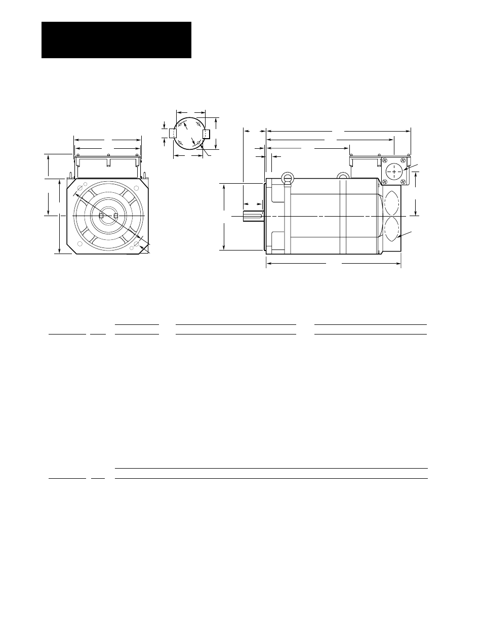
Figure 3.11
1327AB Series B, 1327AC Series A and 1327AD Series B Flange Mount Motor
ES
AK
BE
BB
XM
XC
XN
AH
AC
XL
P
AB
BH
4 -
∅
BF
AJ
1327AC-AFM-02-F
1327AC-AFM-04-F
1327AC-AFM-06-F
1327AC-AFL-08-F
1327AC-AFL-11-F
1327AB-AFL-15-F
1327AB-AFL-19-F
1327AB-AFL-22-F
1327AD-ABL-04-F
1327AD-ABL-06-F
1327AD-ACL-08-F
1327AD-AAK-11-F
1327AD-AAK-15-F
1327AD-AAK-19-F
Catalog Number
174
204
204
250
250
250
250
250
250
250
250
330
384
384
P
337
408
448
410
450
500
550
590
453
491
539
687
666
716
AG
174
204
204
250
250
250
250
250
250
250
250
310
380
380
BH
35
51
51
51
51
51
63
63
49
49
49
61
61
61
AA
148
176
176
199
199
206
206
206
183
183
183
212
280
280
AB
104
124
124
147
147
151
151
151
131
131
131
158
216
216
AC
318
376
416
384
424
493.5
543.5
583.5
398
436
484
667
628
678
XC
192
212
212
212
212
242
242
242
320
320
320
330
385
385
XL
360
426
466
434
474
548
598
638
441
479
527
722
687
737
XN
XM
190
236
276
244
284
328
378
418
265
303
351
491
430
480
Flange Mount Motor
(Dimensions are in millimeters)
∅
AA
AG
1327AC-AFM-02-F
1327AC-AFM-04-F
1327AC-AFM-06-F
1327AC-AFL-08-F
1327AC-AFL-11-F
1327AB-AFL-15-F
1327AB-AFL-19-F
1327AB-AFL-22-F
1327AD-ABL-04-F
1327AD-ABL-06-F
1327AD-ACL-08-F
1327AD-AAK-11-F
1327AD-AAK-15-F
1327AD-AAK-19-F
Catalog Number
28 j6
(+0.009/–0.004)
28 h6
(+0.000/–0.013)
32 h6
(+0.000/–0.016)
48 h6
(+0.000/–0.016)
48 h6
(+0.000/–0.016)
48 h6
(+0.000/–0.016)
55 h6
(+0.000/–0.019)
55 h6
(+0.000/–0.019)
48 h6
(+0.000/–0.016)
48 h6
(+0.000/–0.016)
55 h6
(+0.000/–0.019)
60 h6
(+0.000/–0.019)
70 h6
(+0.000/–0.019)
70 h6
(+0.000/–0.019)
U
60
60
80
110
110
110
110
110
110
110
110
140
140
140
AH
-
49
75
97
97
97
98
98
90
90
90
110
110
110
ES
-
24
(0.0/–0.2)
27
(0.0/–0.2)
42.5
(0.0/–0.2)
42.5
(0.0/–0.2)
42.5
(0.0/–0.2)
49
(0.0/–0.2)
49
(0.0/–0.2)
42.5
(0.0/–0.2)
42.5
(0.0/–0.2)
49
(0.0/–0.2)
53
(0.0/–0.2)
62.5
(0.0/–0.2)
62.5
(0.0/–0.2)
R
-
8 P9
(–0.015/–0.051)
10 P9
(–0.015/–0.051)
14 P9
(–0.018/–0.061)
14 P9
(–0.018/–0.061)
14 P9
(–0.018/–0.061)
16 P9
(–0.018/–0.061)
16 P9
(–0.018/–0.061)
14 P9
(–0.018/–0.061)
14 P9
(–0.018/–0.061)
16 P9
(–0.018/–0.061)
18 P9
(–0.018/–0.061)
20 P9
(–0.022/–0.074)
20 P9
(–0.022/–0.074)
S
185
215
215
265
265
265
265
265
265
265
265
350
400
400
AJ
150 h7
(+0.000/–0.040)
180 h7
(+0.000/–0.040)
180 h7
(+0.000/–0.040)
230 h7
(+0.000/–0.046)
230 h7
(+0.000/–0.046)
230 h7
(+0.000/–0.046)
230 h7
(+0.000/–0.046)
230 h7
(+0.000/–0.046)
230 h7
(+0.000/–0.046)
230 h7
(+0.000/–0.046)
230 h7
(+0.000/–0.046)
300 h7
(+0.000/–0.052)
350 h7
(+0.000/–0.057)
350 h7
(+0.000/–0.057)
AK
Overall
Conduit Box
Shaft and Key
Flange
5
5
5
5
5
5
5
5
5
5
5
5
5
5
BB
15
18
18
20
20
20
20
20
18
18
18
20
22
22
BE
11
14.5
14.5
14.5
14.5
14.5
14.5
14.5
15
15
15
19
24
24
BF
-
8 h9
(+0.0/–0.036)
10 h9
(+0.0/–0.036)
14 h9
(+0.0/–0.043)
14 h9
(+0.0/–0.043)
14 h9
(+0.0/–0.043)
16 h9
(+0.0/–0.043)
16 h9
(+0.0/–0.043)
14 h9
(+0.0/–0.043)
14 h9
(+0.0/–0.043)
16 h9
(+0.0/–0.043)
18 h9
(+0.0/–0.043)
20 h9
(+0.0/–0.052)
20 h9
(+0.0/–0.052)
Key - W
U
S
R
XA
XB
R
Shaft Detail
-
16
22
38
38
38
45
45
38
38
45
50
60
60
XA
-
2 – M6 x 10 deep
4 – M5 x 10 deep
4 – M5 x 10 deep
4 – M5 x 10 deep
4 – M5 x 10 deep
4 – M5 x 10 deep
4 – M5 x 10 deep
4 – M5 x 10 deep
4 – M5 x 10 deep
4 – M5 x 10 deep
4 – M6 x 10 deep
4 – M6 x 10 deep
4 – M6 x 10 deep
XB
-
7 h11
(+0.0/–0.09)
8 h11
(+0.0/–0.09)
9 h11
(+0.0/–0.09)
9 h11
(+0.0/–0.09)
9 h11
(+0.0/–0.09)
10 h11
(+0.0/–0.09)
10 h11
(+0.0/–0.09)
9 h11
(+0.0/–0.09)
9 h11
(+0.0/–0.09)
10 h11
(+0.0/–0.09)
11 h11
(+0.0/–0.11)
12 h11
(+0.0/–0.11)
12 h11
(+0.0/–0.11)
Key - H
Blower
A
A
A
A
A
B
B
B
B
B
B
B
B
B
Series
A
A
A
A
A
B
B
B
B
B
B
B
B
B
Series