Rockwell Automation 8510 AC Spindle Drive System User Manual User Manual
Page 85
Wiring
Chapter 8
8-81
Table 8.F
Motor Current Requirements
Motor
Catalog Number
1327AC-AFM-02-F
1327AC-AFM-04-x
1327AC-AFM-06-x
1327AC-AFL-08-x
1327AC-AFL-11-x
1327AB-AFL-15-x
1327AB-AFL-19-x
1327AB-AFL-22-x
1327AD-ABL-04-x
1327AD-ABL-06-x
1327AD-ABL-08-E
1327AD-ACL-08-F
1327AD-AAK-11-x
1327AD-AAK-15-x
1327AD-AAK-19-x
Power Rating
(Cont. / 30 Minute
kW)
2.2 / 3.7
3.7 / 5.5
5.5 / 7.5
7.5 / 11
11 / 15
15 / 18.5
18.5 / 22
22 / 30
3.7 / 5.5
5.5 / 7.5
7.5 / 11
7.5 / 11
11 / 15
15 / 19
19 / 22
Current Rating
(Cont./30 Minute A)
20 / 27
27 / 33
36 / 43
45 / 59
73 / 91
97 / 112
120 / 135
122 / 153
25 / 34
37 / 45
50 / 68
52 / 68
65 / 87
83 / 102
95 / 110
Wire Size
1, 2
(AWG / mm
2
)
10 / 4.0
8 / 6.0
8 / 10.0
6 / 16.0
3 / 25.0
2 at 4 / 2 at
16.0
3
2 at 3 / 2 at
16.0
3
2 at 3 / 2 at
25.0
3
8 / 6.0
8 / 10.0
6 / 16.0
6 / 16.0
4 / 25.0
2 at 6 / 2 at
16.0
3
2 at 4 / 2 at
16.0
3
1
AWG wire sizes are based on 75
°
C wire. The mm
2
wire sizes are based on 70
°
C wire. Both ratings
are based on 30
°
C ambient.
2
If 90
°
C wire is used, the wire sizes can be reduced about one wire size. Refer to the NEC for proper
wire sizing for higher temperature wire.
3
Due to terminal block size limitations on the drive, run two conductors per phase of the size
indicated.
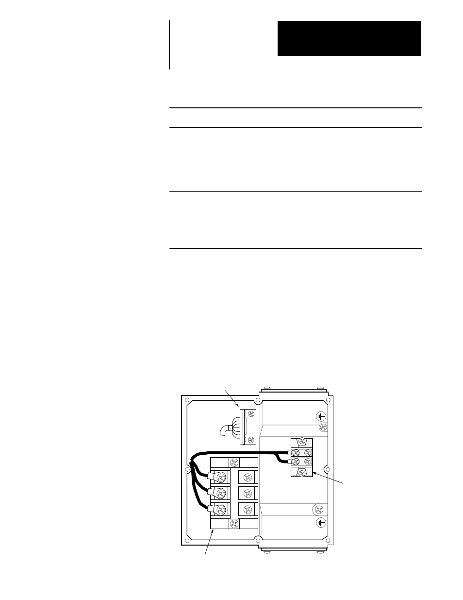
See Figure 8.3 for the configuration of a typical terminal box on a standard
1327AB series motor. The power interconnect wiring between the drive
and a standard 1327AB series motor is shown in the following diagram.
Figure 8.3
Terminal Box – Standard Motor
W
V
U
B1
B2
Motor Power Terminal Block
Fan Power Terminal Block
AMP Connector