Rockwell Automation 8510 AC Spindle Drive System User Manual User Manual
Page 108
Display Panel & Fault Diagnostics
Chapter 10
10-104
Display Description
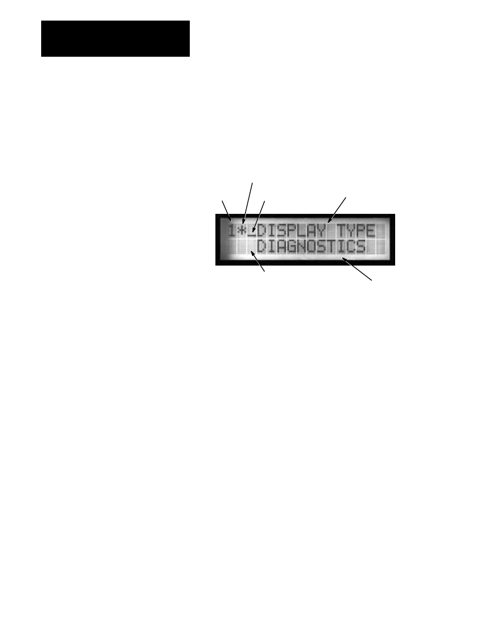
The 8510 display which is used for status and diagnostic messages consists
of a 16 character, 2 line, LCD (Liquid Crystal) display. The display can be
broken into several different sections as shown in Figure 10.2. Refer to the
paragraphs that follow for explanations.
Figure 10.2
LCD Display
Gear Range
Selected by Digital
Inputs
Motor Winding
Selected by Digital
Inputs
Menu Level
Indicator
Menu Information
Menu Level
Indicator (when
applicable)
Menu Information
Line 1, characters 1 & 2 – are used to display the current gear range and
motor winding that have been selected by the digital inputs. Character 1
will show the selected gear range (1-4) and if a 2 speed motor is used,
character 2 will show the motor winding (H = high speed winding, L = low
speed winding). This gear range and motor winding defines the data set
that is currently being used for drive operation.
Line 1, character 3 – is a variable length bar (moving from the bottom up)
that represents the current depth (level) in the menu system.
Line 1, characters 4-16 – are used to display the name of the current menu
level or selected parameter. The menu options or parameter value
associated with the item displayed on line 1 will be displayed on line 2.
Line 2, character 3 – is a variable length bar (moving from the bottom up)
that represents the current depth (level) in the menu system that has been
selected. For each level the user moves down the menu tree, another bar is
added to the display.
Line 2, characters 4-16 – are used to display the options that are available
at the current menu level or the value of the parameter that has been
selected.