Foot mount motor, Dimensions chapter 3, Dimensions are in millimeters) – Rockwell Automation 8510 AC Spindle Drive System User Manual User Manual
Page 33
Dimensions
Chapter 3
3-29
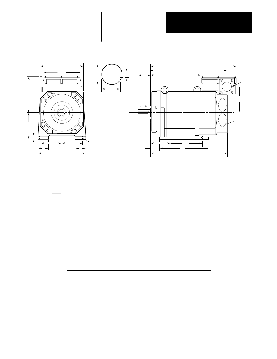
Figure 3.12
1327AB Series B, 1327AC Series A and 1327AD Series B Foot Mount Motor
1327AC-AFM-04-E
1327AC-AFM-06-E
1327AC-AFL-08-E
1327AC-AFL-11-E
1327AB-AFL-15-E
1327AB-AFL-19-E
1327AB-AFL-22-E
1327AD-ABL-04-E
1327AD-ABL-06-E
1327AD-ABL-08-E
1327AD-AAK-11-E
1327AD-AAK-15-E
1327AD-AAK-19-E
Catalog Number
204
204
250
250
250
250
250
250
250
250
310
380
380
P
395
435
401
441
491
541
581
454
492
569
643
661.5
711.5
AG
112
112
160
160
160
160
160
160
160
160
180
225
225
D
1327AC-AFM-04-E
1327AC-AFM-06-E
1327AC-AFL-08-E
1327AC-AFL-11-E
1327AB-AFL-15-E
1327AB-AFL-19-E
1327AB-AFL-22-E
1327AD-ABL-04-E
1327AD-ABL-06-E
1327AD-ABL-08-E
1327AD-AAK-11-E
1327AD-AAK-15-E
1327AD-AAK-19-E
Catalog Number
A
A
A
A
B
B
B
B
B
B
B
B
B
Series
51
51
51
51
51
63
63
49
49
49
61
61
61
AA
176
176
199
199
206
206
206
183
183
183
212
280
280
AB
124
124
147
147
151
151
151
131
131
131
158
216
216
AC
363
403
375
415
484.5
534.5
574.5
399
437
513.5
623
623.5
673.5
XC
212
212
212
212
242
242
242
320
320
320
330
385
385
XL
413
453
425
465
539
589
629
442
480
556.5
678
682.5
732.5
XN
XM
223
263
235
275
319
369
409
266
304
380.5
447
425.5
475.5
28 h6
(+0.000/–0.013)
32 h6
(+0.000/–0.016)
48 h6
(+0.000/–0.016)
48 h6
(+0.000/–0.016)
48 h6
(+0.000/–0.016)
55 m6
(+0.030/+0.011)
55 m6
(+0.030/+0.011)
48 h6
(+0.000/–0.016)
48 h6
(+0.000/–0.016)
55 m6
(+0.030/+0.011)
60 m6
(+0.030/+0.011)
70 m6
(+0.030/+0.011)
70 m6
(+0.030/+0.011)
U
60
80
110
110
110
110
110
110
110
110
140
140
140
N-W
49
70
97
97
97
98
98
90
90
90
110
110
110
ES
220
220
290
290
290
290
290
290
290
290
320
420
420
A
95
95
127
127
127
127
127
127
127
127
139.5
178
178
E
11
10
18
18
18
18
18
16
16
16
16
21
21
G
12
12
14.5
14.5
14.5
14.5
14.5
15
15
15
19
24
24
H
44
44
65
65
65
65
65
47
55
55
55
75
75
J
198
237
235
261
340
365
404
244
278
375
390
425
465
B
100
140
140
178
254
279
318
178
210
305
254
311
349
2F
70
70
108
108
108
108
108
108
108
108
121
149
149
BA
30.5
30.5
43
43
43
43
43
59
59
59
50
73
73
XB
ES
XM
XC
XN
N-W
AC
BA
2F
B
∅
AA
P
D
4 -
∅
H
A
J
J
E
E
AB
G
U
S
R
Shaft Detail
Foot Mount Motor
(Dimensions are in millimeters)
+0.0
-0.5
AG
Overall
Conduit Box
Shaft and Key
Mounting Feet
XB
24
(0.0/–0.2)
27
(0.0/–0.2)
42.5
(0.0/–0.2)
42.5
(0.0/–0.2)
42.5
(0.0/–0.2)
49
(0.0/–0.2)
49
(0.0/–0.2)
42.5
(0.0/–0.2)
42.5
(0.0/–0.2)
49
(0.0/–0.2)
53
(0.0/–0.2)
62.5
(0.0/–0.2)
62.5
(0.0/–0.2)
R
8 P9
(–0.015/–0.051)
10 P9
(–0.015/–0.051)
14 P9
(–0.018/–0.061)
14 P9
(–0.018/–0.061)
14 P9
(–0.018/–0.061)
16 P9
(–0.018/–0.061)
16 P9
(–0.018/–0.061)
14 P9
(–0.018/–0.061)
14 P9
(–0.018/–0.061)
16 P9
(–0.018/–0.061)
18 P9
(–0.018/–0.061)
20 P9
(–0.022/–0.074)
20 P9
(–0.022/–0.074)
S
8 h9
(+0.0/–0.036)
10 h9
(+0.0/–0.036)
14 h9
(+0.0/–0.043)
14 h9
(+0.0/–0.043)
14 h9
(+0.0/–0.043)
16 h9
(+0.0/–0.043)
16 h9
(+0.0/–0.043)
14 h9
(+0.0/–0.043)
14 h9
(+0.0/–0.043)
16 h9
(+0.0/–0.043)
18 h9
(+0.0/–0.043)
20 h9
(+0.0/–0.052)
20 h9
(+0.0/–0.052)
Key - W
7 h11
(+0.0/–0.09)
8 h11
(+0.0/–0.09)
9 h11
(+0.0/–0.09)
9 h11
(+0.0/–0.09)
9 h11
(+0.0/–0.09)
10 h11
(+0.0/–0.09)
10 h11
(+0.0/–0.09)
9 h11
(+0.0/–0.09)
9 h11
(+0.0/–0.09)
10 h11
(+0.0/–0.09)
11 h11
(+0.0/–0.11)
12 h11
(+0.0/–0.11)
12 h11
(+0.0/–0.11)
Key - H
Blower
XL
A
A
A
A
B
B
B
B
B
B
B
B
B
Series