Foot mount motor, Dimensions chapter 3, Dimensions are in millimeters) – Rockwell Automation 8510 AC Spindle Drive System User Manual User Manual
Page 31
Dimensions
Chapter 3
3-27
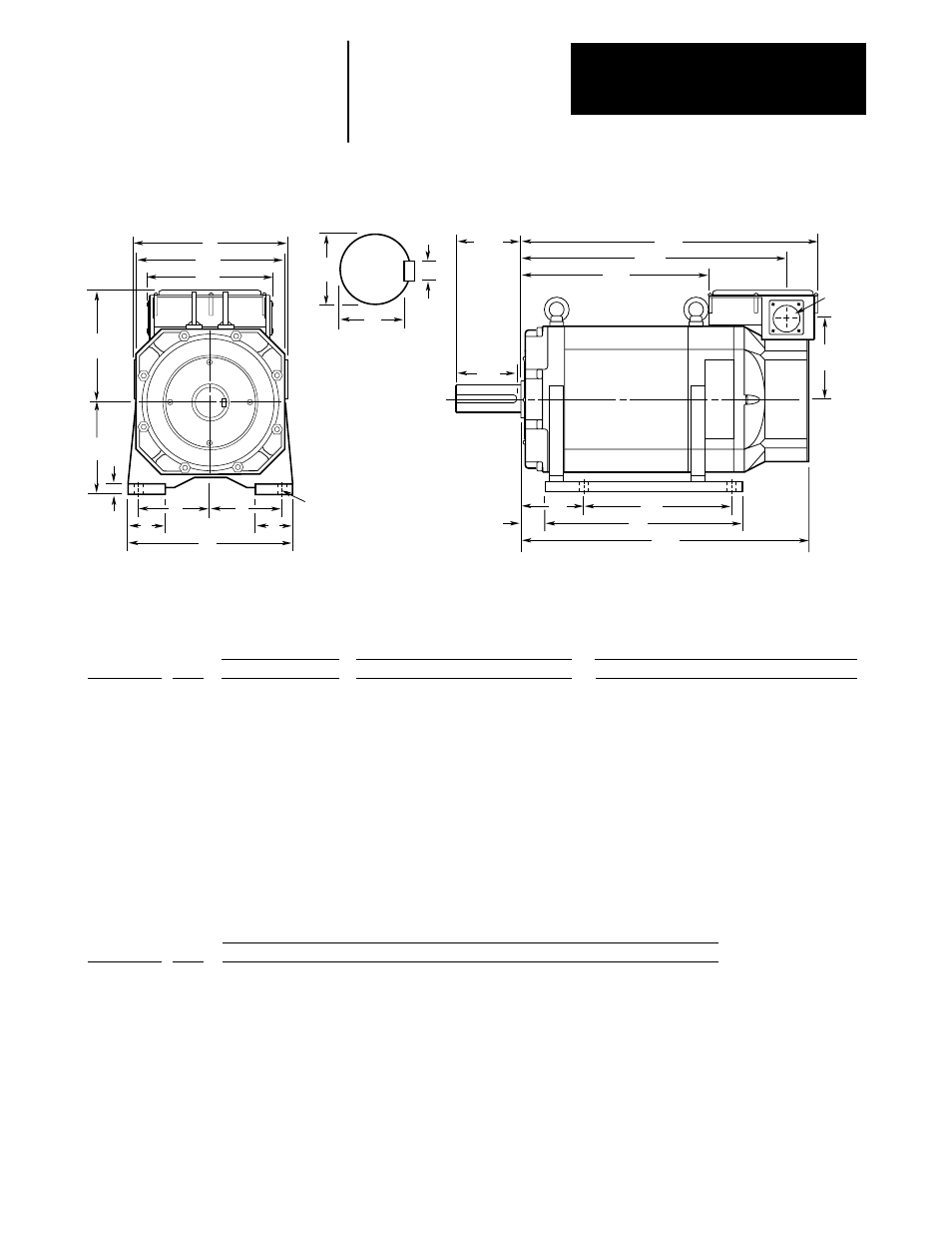
Figure 3.10
1327AB and 1327AD Series A Foot Mount Motor
1327AB-AFM-04-E
1327AB-AFM-06-E
1327AB-AFL-08-E
1327AB-AFL-11-E
1327AB-AFL-15-E
1327AB-AFL-19-E
1327AB-AFL-22-E
1327AD-ABL-04-E
1327AD-ABL-06-E
1327AD-ABL-08-E
1327AD-AAK-11-E
1327AD-AAK-15-E
1327AD-AAK-19-E
Catalog Number
211
211
258
258
250
250
250
250
250
250
310
380
380
P
406
435
408
448
498
549
589
454
492
569
643
661.5
711.5
AG
112
112
160
160
160
160
160
160
160
160
180
225
225
D
204
204
250
250
250
250
250
250
250
250
310
380
380
BH
1327AB-AFM-04-E
1327AB-AFM-06-E
1327AB-AFL-08-E
1327AB-AFL-11-E
1327AB-AFL-15-E
1327AB-AFL-19-E
1327AB-AFL-22-E
1327AD-ABL-04-E
1327AD-ABL-06-E
1327AD-ABL-08-E
1327AD-AAK-11-E
1327AD-AAK-15-E
1327AD-AAK-19-E
Catalog Number
A
A
A
A
A
A
A
A
A
A
A
A
A
Series
51
51
51
51
51
63
63
49
49
49
61
61
61
AA
178
178
202
202
207
207
207
183
183
183
212
280
280
AB
126
126
150
150
152
152
152
131
131
131
158
216
216
AC
365
405
372
412
487.5
537.5
577.5
399
437
513.5
623
623.5
673.5
XC
214
214
214
214
241
241
241
320
320
320
330
385
385
XL
415
455
422
462
542
592
632
442
480
556.5
678
682.5
732.5
XN
XM
225
265
232
272
322
372
412
266
304
380.5
447
425.5
475.5
28 h6
(+0.000/–0.013)
32 h6
(+0.000/–0.016)
48 h6
(+0.000/–0.016)
48 h6
(+0.000/–0.016)
48 h6
(+0.000/–0.016)
55 m6
(+0.030/+0.011)
55 m6
(+0.030/+0.011)
48 h6
(+0.000/–0.016)
48 h6
(+0.000/–0.016)
55 m6
(+0.030/+0.011)
60 m6
(+0.030/+0.011)
70 m6
(+0.030/+0.011)
70 m6
(+0.030/+0.011)
U
60
80
110
110
110
110
110
110
110
110
140
140
140
N-W
49
70
97
97
97
98
98
90
90
90
110
110
110
ES
220
220
290
290
290
290
290
290
290
290
320
420
420
A
95
95
127
127
127
127
127
127
127
127
139.5
178
178
E
11
10
18
18
18
18
18
16
16
16
16
21
21
G
12
12
15
15
14.5
14.5
14.5
15
15
15
19
24
24
H
44
44
65
65
65
65
65
47
55
55
55
75
75
J
198
238
235
261
340
365
404
244
278
375
390
425
465
B
100
140
140
178
254
279
318
178
210
305
254
311
349
2F
70
70
108
108
108
108
108
108
108
108
121
149
149
BA
27.5
27.5
43
43
43
43
43
59
59
59
50
73
73
XB
ES
XM
XC
XN
N-W
AC
BA
2F
B
∅
AA
BH
P
D
4 -
∅
H
XL
A
J
J
E
E
AB
G
U
S
R
Shaft Detail
Foot Mount Motor
(Dimensions are in millimeters)
+0.0
-0.5
AG
Overall
Conduit Box
Shaft and Key
Mounting Feet
XB
24
(0.0/–0.2)
27
(0.0/–0.2)
42.5
(0.0/–0.2)
42.5
(0.0/–0.2)
42.5
(0.0/–0.2)
49
(0.0/–0.2)
49
(0.0/–0.2)
42.5
(0.0/–0.2)
42.5
(0.0/–0.2)
49
(0.0/–0.2)
53
(0.0/–0.2)
62.5
(0.0/–0.2)
62.5
(0.0/–0.2)
R
8 P9
(–0.015/–0.051)
10 P9
(–0.015/–0.051)
14 P9
(–0.018/–0.061)
14 P9
(–0.018/–0.061)
14 P9
(–0.018/–0.061)
16 P9
(–0.018/–0.061)
16 P9
(–0.018/–0.061)
14 P9
(–0.018/–0.061)
14 P9
(–0.018/–0.061)
16 P9
(–0.018/–0.061)
18 P9
(–0.018/–0.061)
20 P9
(–0.022/–0.074)
20 P9
(–0.022/–0.074)
S
8 h9
(+0.0/–0.036)
10 h9
(+0.0/–0.036)
14 h9
(+0.0/–0.043)
14 h9
(+0.0/–0.043)
14 h9
(+0.0/–0.043)
16 h9
(+0.0/–0.043)
16 h9
(+0.0/–0.043)
14 h9
(+0.0/–0.043)
14 h9
(+0.0/–0.043)
16 h9
(+0.0/–0.043)
18 h9
(+0.0/–0.043)
20 h9
(+0.0/–0.052)
20 h9
(+0.0/–0.052)
Key - W
7 h11
(+0.0/–0.09)
8 h11
(+0.0/–0.09)
9 h11
(+0.0/–0.09)
9 h11
(+0.0/–0.09)
9 h11
(+0.0/–0.09)
10 h11
(+0.0/–0.09)
10 h11
(+0.0/–0.09)
9 h11
(+0.0/–0.09)
9 h11
(+0.0/–0.09)
10 h11
(+0.0/–0.09)
11 h11
(+0.0/–0.11)
12 h11
(+0.0/–0.11)
12 h11
(+0.0/–0.11)
Key - H
A
A
A
A
A
A
A
A
A
A
A
A
A
Series