Display panel & fault diagnostics – Rockwell Automation 8510 AC Spindle Drive System User Manual User Manual
Page 107
10
Chapter
10-103
Display Panel & Fault Diagnostics
Chapter Objectives
This chapter explains the 8510 display panel and how it is used to show
different measurements and perform fault diagnostics. Included is an
explanation of the display and descriptions of the various parameters that
can be displayed.
Menu Format and Conventions
The menu system is based on the 16 character by 2 line display used in the
8510. The menu is arranged in a tree format (see Figure 10.1) to allow easy
access to any item. Menu items will be displayed two different ways:
1) UPPER CASE letters (capitals) indicate the item is a menu heading
with a group of sub-menus or parameter names below it.
2) Initial Capital letters indicate the item is the name of a parameter.
In this manual, any text that shows the exact display format of a menu or
parameter name is shown in italics.
Any text that shows the exact display format of a parameter data value or
selection is enclosed in “quotes.”
When power is first applied to the drive or a reset is performed after a
fault, the software version number is indicated on the display during the
initial diagnostic checks. Have this software version number available
before contacting the factory concerning a malfunctioning drive.
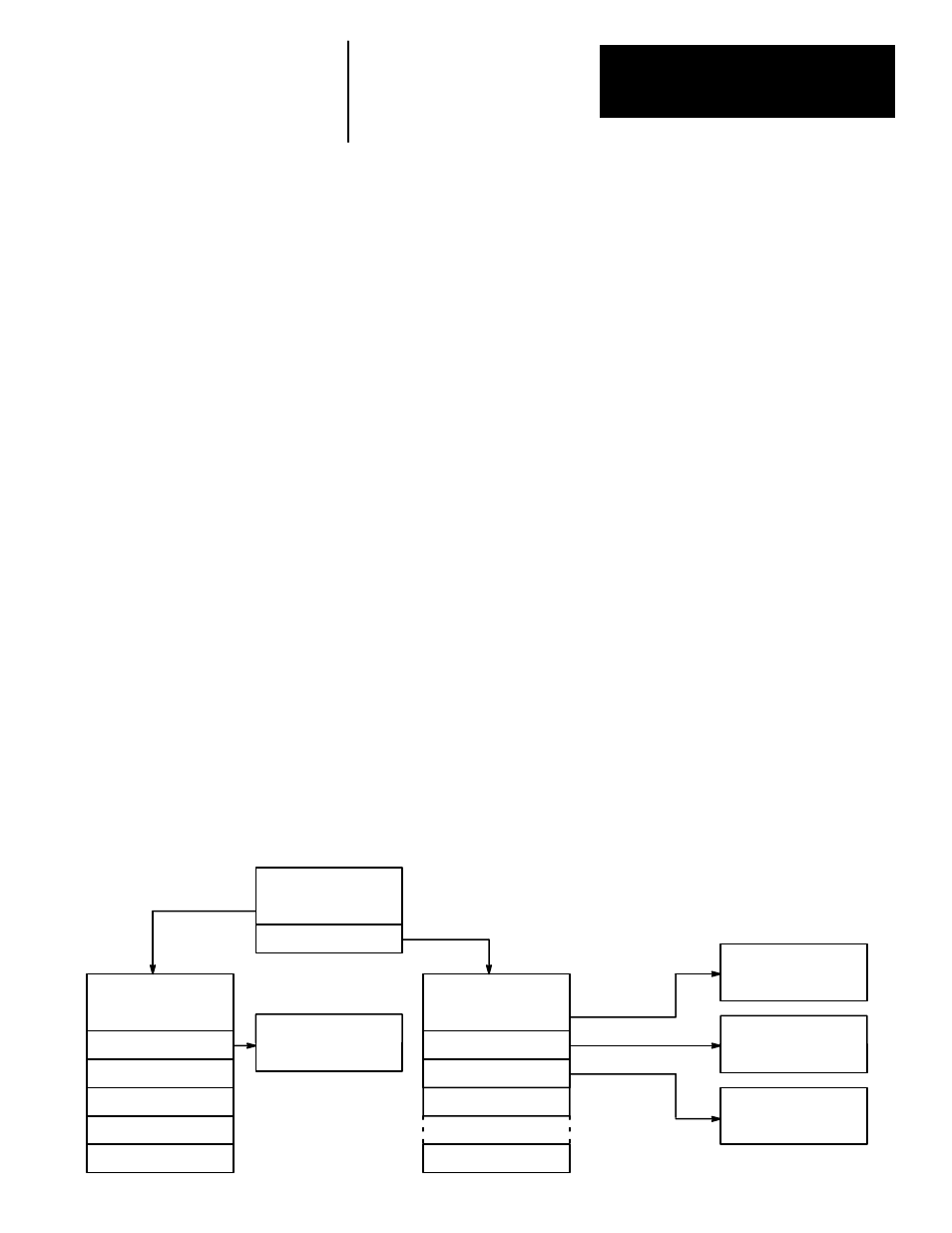
After power is applied, the DISPLAY TYPE menu will be shown. This
menu allows selection of the METER DISPLAY or DIAGNOSTICS mode.
Figure 10.1
“Display Type” Menu Tree
DISPLAY TYPE
2L
METER DISPLAY
2L
Motor Speed
Spindle Speed
METER DISPLAY
DIAGNOSTICS
DIAGNOSTICS
2L
I/O Outputs
I/O Inputs
% Load
% Torque
Power Output
Orient Error
Current Fault
Spindle Speed
2L
RPM +2387
Current Fault:
2L
AC PHASE LOSS
I/O Inputs:
2L
JK-MNO--RST-V
I/O Outputs:
2L
AB-DE--HI
Hist - #1
Hist - #8
..