Rockwell Automation 8510 AC Spindle Drive System User Manual User Manual
Page 80
Wiring
Chapter 8
8-76
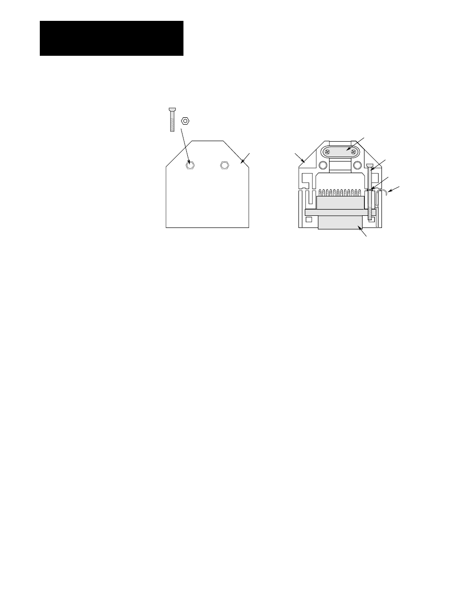
Figure 8.1
Connector Wiring
Cable Clamp
Long Screw
Washer
Clip
Connector Housing
Connector
Short Screw & Nut
Honda Connector Wiring and Assembly
Refer to the following information and the instruction sheet provided with
the connector kit for assembly procedure.
1. Disassemble the connector by removing the 2 short screws and nuts
(see Figure 8.1). Since the connector contains a number of small pieces,
care should be taken during disassembly.
2. Prepare cable and wire ends. Using a rosin core solder, carefully solder
wires to connector using the cable information provided in this chapter.
3. Install cable clamp around cable(s). To allow positioning, do not
tighten clamp completely.
4. Place connector into housing and slide cable clamp to position shown
in Figure 8.1. Tighten cable clamp.
5. Install the 2 long screws and washers through the holes in the
connector. Position screws and washers as shown in Figure 8.1.
6. Place clips into housing and secure remaining housing piece over
assembly using the 2 short screws and nuts previously removed.
The maximum wire size that the terminals in the Honda connector can
accept is 24 AWG (0.28 mm
2
). For each connector, the cable type
recommended in this chapter, or an equivalent, must be used to assure
proper system operation.
If larger wire sizes are preferred, the optional Termination Panels will
allow use of up to 16 AWG (1 mm
2
) wire. If larger cable sizes are used, the
cable configuration and shielding must conform to that specified for the
standard cable.
All shields must be terminated in accordance with the following wiring
diagrams. If one end of a shield is to be left open, take care to insulate and
properly isolate the open end of shield to avoid shorting it to ground.