Rockwell Automation 8510 AC Spindle Drive System User Manual User Manual
Page 84
Wiring
Chapter 8
8-80
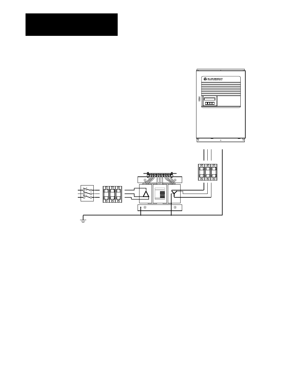
Figure 8.2
Recommended AC Input Power Connection
8510
DIGITAL AC SPINDLE DRIVE
Mode
Scroll +
Select
Scroll –
CAT. NO.
FREQUENCY
POWER RATING
PRIMARY VOLTAGE
SECONDARY VOLTAGE
INSULATION CLASS
NO. OF PHASES
VENDOR PART NO.
Optional Isolation Transformer
or Autotransformer
Disconnect and Branch Circuit
Overcurrent Protection
Supplied by User
8510SA Fuse Kit
Drive Component
Overcurrent Protection
AC
Incoming
Power
Site Ground
R S T
E
Power From 8510 Drive To The 1327A Series Motor
The motor power output terminals are located at the bottom of the drive as
shown in Figure 7.3. Motor current requirements and wire size are
dependent on the specific motor type. Table 8.F defines the drive output
current requirements when used with the various motor catalog numbers.
Wire sizes are selected per NFPA-79 and IEC-204 for wires in a cable or
raceway and are based on 75
°
C wire (70
°
C for IEC-204).
The motor fan should be wired to the motor fan power terminals on the
bottom of the drive (see Figure 7.3 for terminal locations). The terminals in
both the drive and motor use M4 screws. The motor fan current ranges
from 0.3A in the smallest motor to 1.2A in the largest motor. The power
output terminals are fused in the drive with 5A fuses. A #20
AWG/0.50 mm
2
wire is adequate for the motor fan wiring.