Wiring chapter 8, Figure 8.7 t ypical 9/series cnc interconnect, 8510 drive – Rockwell Automation 8510 AC Spindle Drive System User Manual User Manual
Page 89: I/o board control i/o, Typical e-stop string e-stop terminal block bt101, E-stop status relay (user supplied)
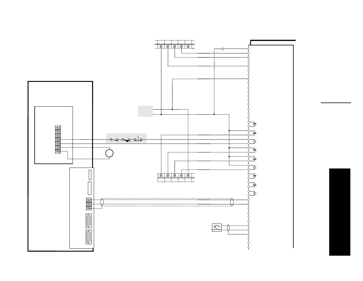
Wiring
Chapter 8
8-85
Figure 8.7
T
ypical
9/Series CNC Interconnect
8510 Drive
Coast-to-Stop
Drive Enable
Drive Reset
CN9-1
CN9-2
CN9-3
Digital Ground
Forward Run
Reverse Run
CN9-4
CN9-5
CN9-6
Low Torque Limit Select
CN9-7
Digital Ground
CN9-8
Servo Input Scaling - Low/High
Orient Command
Digital Ground
CN9-10
CN9-11
CN9-12
Gear Ratio Active #1
Gear Ratio Active #2
CN9-13
CN9-14
Motor Winding Select - Low/High
CN9-15
Digital Ground
CN9-16
Spindle/Servo Mode Select
CN9-9
Current Motor Winding Selected
Drive Ready
CN9-17
CN9-18
CN9-19
Hard Fault
CN9-20
CN9-21
CN9-22
Soft Fault
CN9-23
CN9-24
At Speed Indicator
CN9-26
CN9-27
CN9-28
Speed Level Indicator
Load Level Indicator
CN9-29
CN9-30
CN9-31
CN9-32
In-Position
CN9-33
Zero Speed Indicator
CN9-25
CN9-34
CN9-35
CN9-36
Analog Input #2
Shield
CN9-38
CN9-39
CN9-40
Analog Output #1
Shield
CN9-41
CN9-42
CN9-43
Analog Output #2
CN9-44
CN9-45
Shield
CN9-37
Shield
CN9-46
Analog Input #1
Analog Input #1 Return
Analog Input #2 Return
Analog Output #1 Return
Analog Output #2 Return
I/O Board
Control I/O
Accel/Decel Rate Select
CN9-47
User Supplied
Speed Meter
User's E-Stop
Status Relay (K1)
VDC1 A12
A13 A14 A15
A01 A02 A03 A04 COM
3
2
1
3
2
1
6
5
4
7
Typical E-Stop String
E-Stop
Terminal Block
BT101
+24V DC
Common
User Supplied
Power Source
Analog Servo
Module
8500-ASM3
Sub Processor Board
9/Series CNC
Digital I/O Module (1/2)
8500-E154
Digital I/O Module (1/2)
8500-E154
K1
E-Stop Status Relay
(User Supplied)