3ć14, Select optional configurations – Rockwell Automation 1771-QDC, D17716.5.86(Passport) PLASTIC MOLDING MODULE User Manual
Page 52
Configure the QDC Module's I/O
Chapter 3
3-14
You also have the option of configuring the following QDC features:
Use this Option:
For this Benefit:
Software Travel Limits
to guard against damaging the nozzle assembly or seals
Pressure Alarm Time Delay
to warn of excessive pressure without nuisance alarms
Digital Filter
to compensate for noise on position inputs
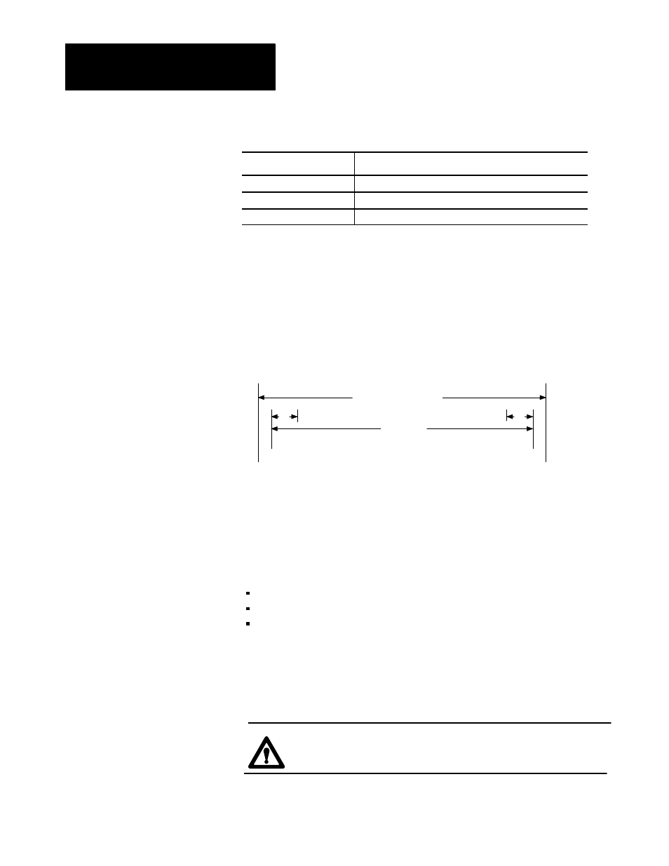
Configure Software Travel Limits
You may want to use the software restrictions, Figure 3.1, to stop the travel
of your ram (screw) or clamp before either reaches its maximum limits
(configured earlier in this chapter).
Figure 3.1
Software Restrictions
Physical Travel Range
Max Position Min Position
d
d
Max SWTL Min SWTL
d = deadband
Safe Zone
Important: The orientation shown (movement left to right) is for clamp
SWTLs. By convention, ram (screw) orientation is reversed.
During normal machine operation and whenever your cylinder travels
outside the safe zone (outside the specified software travel limits, SWTL),
the QDC module:
sets an alarm status bit
forces its outputs to zero
ignores all profile commands (except set-output and jogs) until you jog
the cylinder back through the deadband into the safe zone at either end
The deadband guards against sensor noise flickering the SWTL alarms and
requires that the operator jog the cylinder a set distance away from the
software overtravel limit. We recommend a value of 00.10 inch as a
starting deadband. Your sensor may require a greater deadband.
ATTENTION: The QDC module ignores SWTL alarms when
jogging or when performing a set-output operation.
Select Optional
Configurations