Rockwell Automation 1771-QDC, D17716.5.86(Passport) PLASTIC MOLDING MODULE User Manual
Page 15
Overview of Inject and Clamp Mode
Chapter 1
1-3
Injection Phase
You can vary the velocity of the ram (screw), or the pressure driving it, so
the leading edge of the melt moves through the mold cavity at the desired
speed. The pattern of velocity or pressure variation during injection is
called the injection profile. The QDC module lets you chose from four
different injection profiles:
velocity vs. position
pressure-limited velocity vs. position
pressure vs. position
pressure vs. time
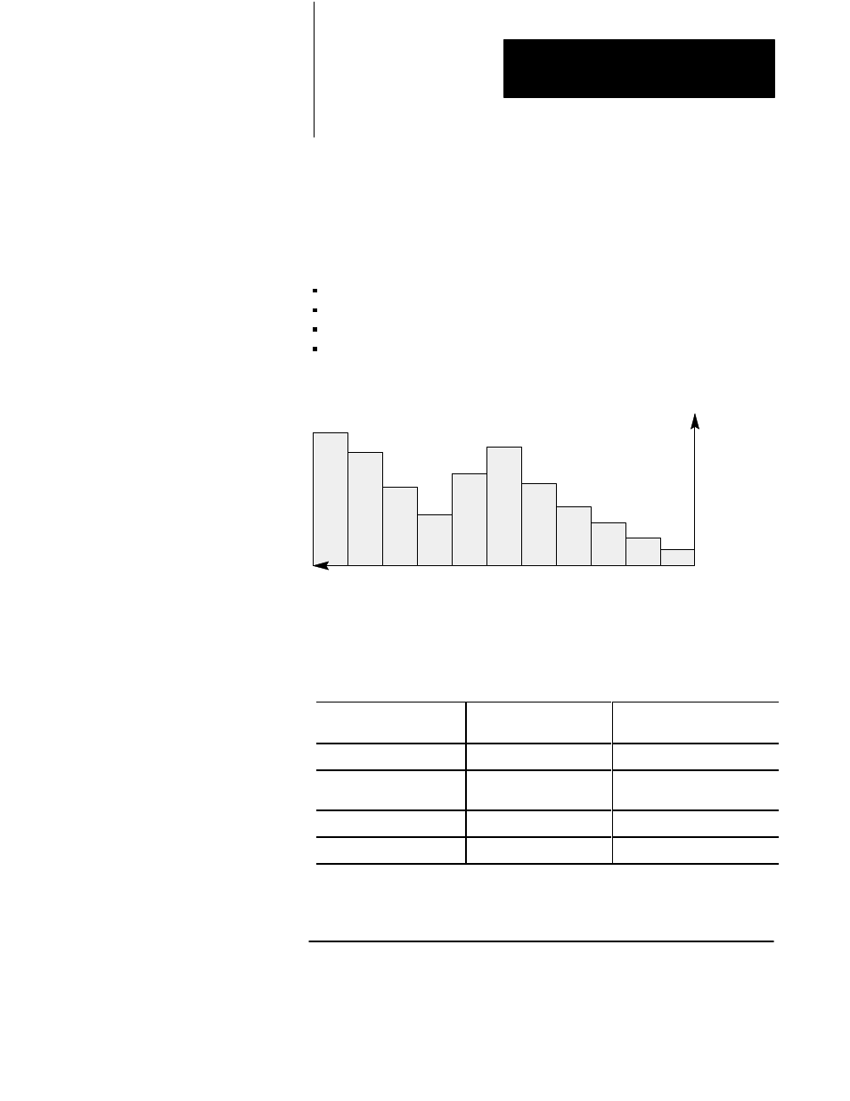
Figure 1.2
Example Injection Profile
11
10
9
8
7
6
5
4
3
2
1
Position or Time
Velocity or Pressure
You enter setpoints to create a profile. You can select from 1 to 11
segments of position or time. Segment numbers represent the order of
operation. By convention the ram (screw) injects plastic by moving from
right to left.
With this Profile:
You Control Injection:
With up to 11 Segments
Distributed over the:
Velocity vs. Position
Speed
Length of the shot
PressureĆlimited
1
Velocity vs. position
Speed with a
maximum pressure
Length of the shot
Pressure vs. Position
Pressure
Length of the shot
Pressure vs. Time
Pressure
Time for a shot
1
PressureĆlimited velocity vs. position profile differs from the velocity vs. position profile as follows:
During any segment, if the pressure exceeds a preset limit, the module switches to PID pressure
control with the pressure limit as the setpoint. Then if velocity exceeds the velocity setpoint, the
module returns to velocity control.