Download mcc values to the qdc module, Configure the qdc module's i/o chapter 3, Enter mcc values into your plcć5 data table – Rockwell Automation 1771-QDC, D17716.5.86(Passport) PLASTIC MOLDING MODULE User Manual
Page 43
Enter Your Initial Values Here
Configure the QDC Module's I/O
Chapter 3
3-5
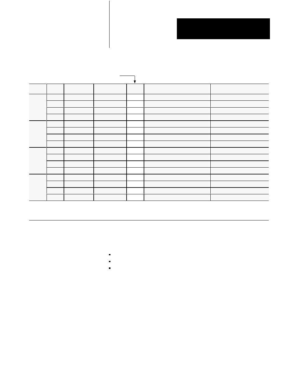
Worksheet 3ĆD
Determine Initial SensorĆconfiguration Values
Input
Line
Control Word
ProĆSet 600 Addr. Value
Description
Units
1
1
MCC09
N40:5
0
Minimum Screw Position
Screw Axis Measured from zero
1
2
MCC10
N40:6
Maximum Screw Position
Screw Axis Measured from zero
1
3
MCC11
N40:7
Analog Signal @ Min Screw Position
Input Signal Range
2
4
MCC12
N40:8
Analog Signal @ Max Screw Position
Input Signal Range
2
2
5
MCC17
N40:13
0
Minimum Screw Pressure
Screw Pressure
3
6
MCC18
N40:14
Maximum Screw Pressure
Screw Pressure
3
7
MCC19
N40:15
Analog Signal @ Min Screw Pressure
Input Signal Range
2
8
MCC20
N40:16
Analog Signal @ Max Screw Pressure
Input Signal Range
2
3
9
MCC23
N40:19
0
Minimum Clamp Position
Clamp Axis Measured from zero
1
10
MCC24
N40:20
Maximum Clamp Position
Clamp Axis Measured from zero
1
11
MCC25
N40:21
Analog Signal @ Min Clamp Position
Input Signal Range
2
12
MCC26
N40.22
Analog Signal @ Max Clamp Position
Input Signal Range
2
4
13
MCC31
N40:27
0
Minimum Clamp Pressure
Clamp Pressure
3
14
MCC32
N40:28
Maximum Clamp Pressure
Clamp Pressure
3
15
MCC33
N40:29
Analog Signal @ Min Clamp Pressure
Input Signal Range
2
16
MCC34
N40:30
Analog Signal @ Max Clamp Pressure Input Signal Range
2
1
Incremental Distance
2
Input Signal Range
3
Pressure
00.00 to 99.99in 00.00 to 10.00VDC or
0000 to 9999 PSI
000.0 to 999.9mm 01.00 to 05.00VDC or 000.0 to 999.9 Bar
04.00 to 20.00MADC
Use this download procedure now and later in this chapter. The procedure
requires you to complete the following general steps:
enter MCC values into the PLC-5 data table
download them to the QDC module (PLC-5 processor in run mode)
correct any data entry (programming) errors
Next we describe the general steps:
Enter MCC Values into Your PLCĆ5 Data Table
With your programming terminal, enter values from Worksheet 3-A thru
Worksheet 3-D into your PLC-5 data table as follows:
1. Switch the PLC-5 processor to program mode.
2. Display your PLC-5 data table.
3. Locate the data file for storing the MCC block. PLC-5 data table
word addresses are listed on the worksheets.
Download MCC Values
to the QDC Module