Rockwell Automation 1771-QDC, D17716.5.86(Passport) PLASTIC MOLDING MODULE User Manual
Page 164
Span Your Valves
Chapter 9
9-7
What You Have Accomplished
The valve spanning procedure you just completed has defined the:
range of pressure available during low pressure close
end-of-range maximum and minimum signal levels for linear control of
the clamp LPC valve in open-loop control
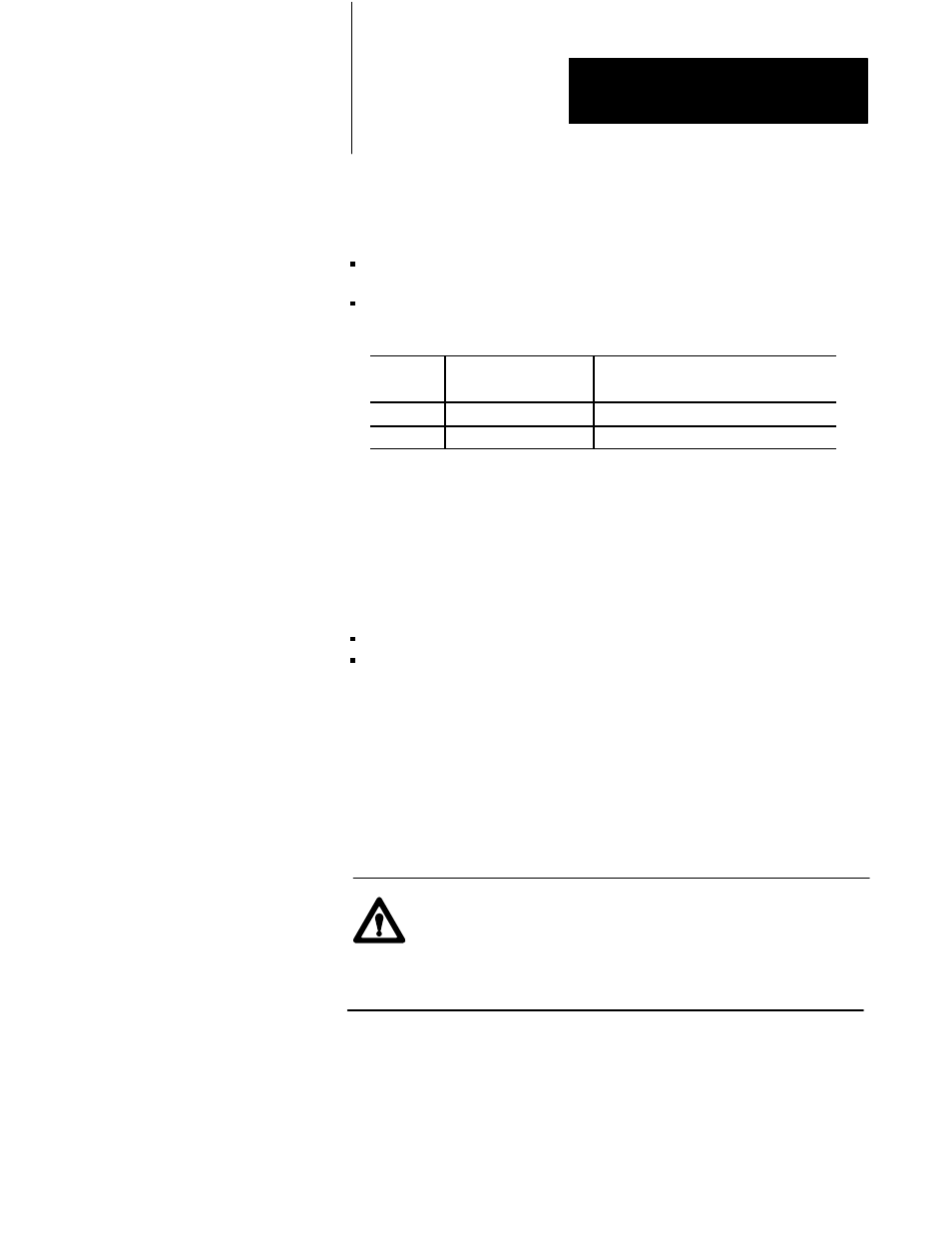
For this
range limit
When trying to obtain
the pressure in:
The QDC module drives the selected
pressure valve to % output signal in:
Minimum
LPC41
LPC43
Maximum
LPC42
LPC44
Now for the open-loop LPC profile, the QDC module assumes a linear
relationship between LPC clamp pressure and signal output.
Set Tonnage on Hydraulic Clamps or Hold Pressure on Toggle Clamps
Once the clamp has completed low pressure close, use the LPC
end-of-profile set-output values to:
build tonnage on your hydraulic clamp
lock up your toggle clamp
1.
Jog your clamp to the full close position (mold halves mated).
2.
Enter a value corresponding to minimum pressure into the set-output
word DYC09-12 (N40:121-124) that corresponds to your clamp-
tonnage or lock-up pressure valve.
3.
Copy the other three set-output values from LPC33-36
(N43:209-212) to DYC09-12 (N40:121-124), values that you would
normally use during tonnage (or lock up)
ATTENTION: A value of 0 entered in your data table does not
necessarily correspond to zero pressure or flow. For example, a
bi-directional valve would require a set-output value of 50%
(5000) to obtain 0 PSI. Amplifier electronics or valve spools
may also allow pressure or flow at 0 volts signal input.
4.
Align all other machine hydraulics to simulate clamp tonnage or
lock-up for a toggle clamp. For example, enable required pumps and
align required valves.