Layout – Sensaphone 2800 User Manual
Page 21
Chapter 1: Introduction
19
LAYOUT
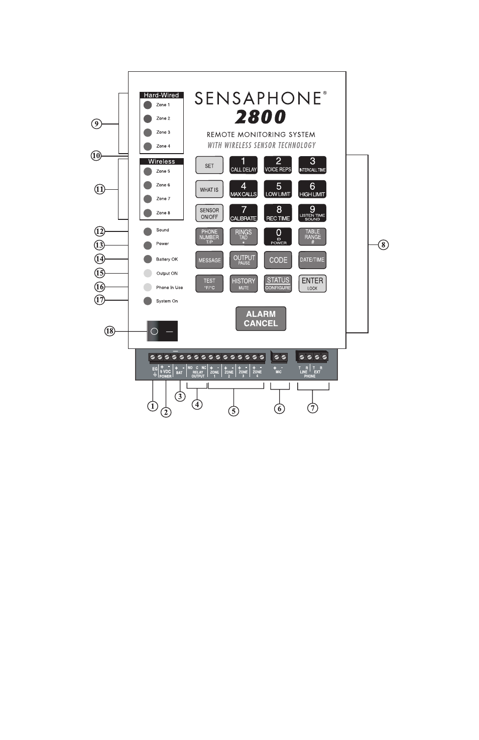
Figure 1: 2800 diagram
1. Grounding Terminal
2. 9vdc Power Terminals
3. Battery Terminals
4. Relay Output Terminals
5. 4 Zone Terminals
6. External Mic Terminals
7. Phone Network/Extension
Terminals
8. Programming Keypad
9. Hard-Wired Alarm Zone
LEDs
10. Microphone
(located behind panel)
11. Wireless Alarm Zone LEDs
12. Sound LED
13. Power LED
14. Battery OK LED
15. Output ON LED
16. Phone-in-use LED
17. System On LED
18. On/Off Switch