Incremental encoder, Encoder counting direction, Rotary encoder function test – NORD Drivesystems BU0505 User Manual
Page 60: Incremental encoder data sheet
SK 54xE – Users Manual for Frequency Inverters
60
BU 0505 GB-1013
For longer cable lengths the cable cross-section must be selected large enough so that the voltage
drop in the cable is not too great. This particularly affects the supply cable, in which the cross-section
can be increased by connecting several conductors in parallel.
Unlike incremental encoders, for sine encoders or SIN/COS encoders the signals are not in the form
of pulses, but rather in the form of sine signals (shifted by 90°).
Note
Encoder counting direction
The counting direction of the incremental encoder must correspond to that of the motor. Therefore, depending on
the rotation direction of the encoder to the motor (possibly reversed), a negative number must be set in parameter
P301.
Note
Rotary encoder function test
The voltage difference between tracks A and B can be measured with the aid of parameter P709 [-09] and [-10]. If
the incremental encoder is rotated, the value of both tracks must jump between -0.8V and 0.8V. If the voltage only
jumps between 0 and 0.8V the relevant rack is faulty. The position can no longer be determined via the
incremental encoder. We recommend replacement of the encoder!
Pos : 80 /Anl eitungen/ Elektroni k/FU und Start er/ 2. M ont age und Ins tall ati on/ 2. 11 F arb- und Kontaktbel egung für Dr ehg eber- I nkrement algeber [ SK 5xxE] @ 1\ mod_1331216115763_388.doc x @ 17854 @ 5 @ 1
Incremental encoder
According to the resolution (pulse number), incremental encoders generate a defined number of
pulses for each rotation of the encoder shaft (Track A / Track A inverse) With this, the precise speed
of the encoder or motor can be measured by the frequency inverter. By the use of a second track (B /
B inverse) shifted by 90° (¼ period), the direction of rotation can also be determined.
The supply voltage for the encoder is 10-30V. The voltage source can be an external source or the
internal voltage (according to the frequency inverter version: 12V /15V /24V).
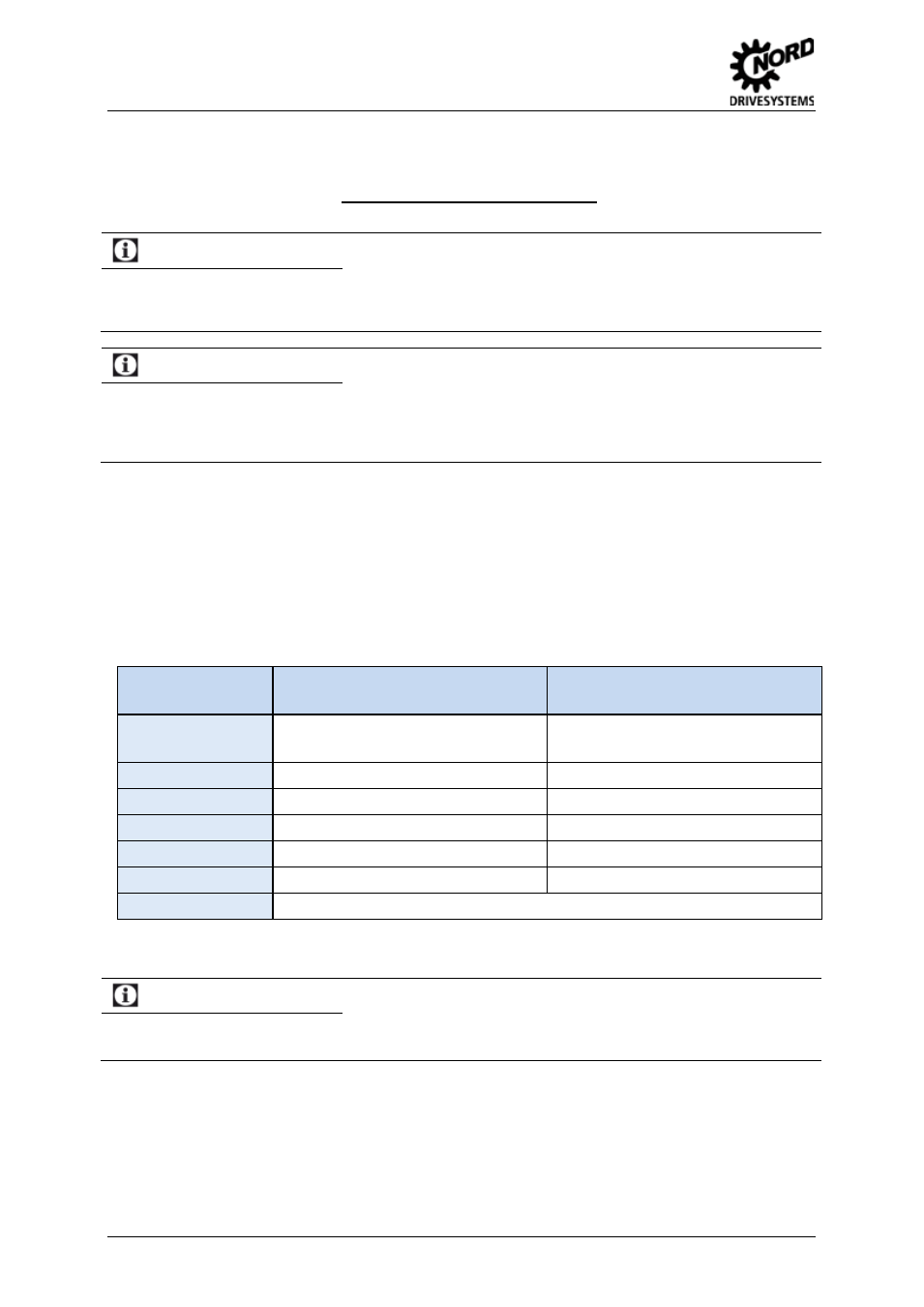
Function
Cable colours,
for incremental encoder
Connections for SK 53xE
Terminal block X5 or X6
10-30V supply
brown / green
42(/44 /49)
15V (/24V /12V)
0V supply
white / green
40 GND/0V
Track A
brown
51 ENC A+
Track A inverse
green
52 ENC A-
Track B
grey
53 ENC B+
Track B inverse
pink
54 ENC B-
Cable shield
connected to a large area of the frequency inverter housing or shielding angle
Table 21: Colour and contact assignments for NORD TTL incremental encoders
Note
Incremental encoder data sheet
If there are deviations from the standard equipment (Type 5820.0H40, 10-30V encoder, TTL/RS422) for the
motors, please note the accompanying data sheet or consult your supplier.
Pos : 81 /Anl eitungen/ Elektroni k/FU und Start er/ 2. M ont age und Ins tall ati on/ 2. 11 F arb- und Kontaktbel egung für Dr ehg eber- Si nus - Geber [SK 54xE] @ 1\ mod_1331216120711_388.doc x @ 17878 @ 5 @ 1