5 parameters – NORD Drivesystems BU0505 User Manual
Page 101
5 Parameters
BU 0505 GB-1013
101
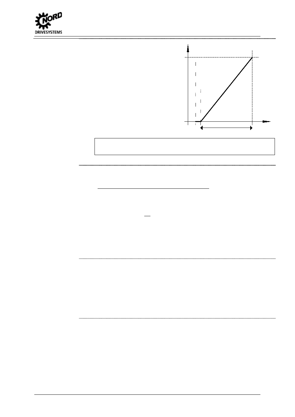
2 = 0 – 10V monitored: If the
minimum adjusted setpoint
(P402) is undershot by 10% of the
difference value from P403 and
P402, the FI output switches off.
Once the setpoint is greater than
[P402 - (10% * (P403 - P402))], it
will deliver an output signal again.
f / Hz
P104
(fmin)
P105
(fmax)
P
403
=
10.
0V
P
402
=
2.
0V
= 8.0V
U/V
O
F
F
=
2.
0V
-
10%
*
8.
0V
=
1.
2V
E.g. setpoint 4-20 mA: P402: Adjustment 0 % = 1 V; P403: Adjustment 100 % = 5 V; -
10 % corresponds to -0.4 V; i.e. 1...5 V (4...20 mA) normal operating zone, 0.6...1 V =
minimum frequency setpoint, below 0.6 V (2.4 mA) output switches off.
3 = - 10V – 10V: If a setpoint smaller than the programmed adjustment 0% (P402) is present,
this can cause a change in direction rotation. This allows rotation direction reversal using
a simple voltage source and potentiometer.
E.g. internal setpoint with rotation direction change: P402 = 5 V, P104 = 0 Hz,
Potentiometer 0-10 V
à Rotation direction change at 5 V in mid-range setting of the
potentiometer.
At the moment of reversal (hysteresis =
± P505), the drive stands still when the minimum
frequency (P104) is smaller than the absolute minimum frequency (P505). A brake that is
controlled by the FI will not have entered the hysteresis range.
If the minimum frequency (P104) is greater than the absolute minimum frequency (P505),
the drive reverses when the minimum frequency is reached. In the hysteresis range
±
P104, the FI supplies the minimum frequency (P104), the brake controlled by the FI is not
applied.
NOTE:
The function -10 V – 10 V is a description of the method of function and not a
reference to a physical bipolar signal (see example above).
4 = 0 – 10V with error 1, "0 – 10V with switch-off on error 1":
If the 0% adjustment value in (P402) is undershot, the error message 12.8 "Analog In Min
Undershot" is activated.
If the 100% adjustment value in (P402) is exceeded, the error message 12.9 "Analog In
Max Exceeded" is activated.
Even if the analog value is outside the limits defined in (P402) and (P403), the setpoint is
limited to 0 - 100%.
The monitoring function only becomes active if there is an enabling signal present and
the analog value has reached the valid range (≥(P402) or ≤(P403)) for the first time
(example: build-up of pressure after a pump is switched on).
5 = 0 – 10V with error 2, "0 – 10V with switch-off on error 2":
See setting 4 ("0 - 10V with error switch off 1“), however:
In this setting the monitoring function only becomes active if an enable signal is present
and the time during which the error monitoring is suppressed has elapsed. This
suppression time is set in parameter (P216).
Pos : 182 /Anleit ungen/5. / 6. Parametrier ung [BU 0500 / BU 0200]/ Par ameter/ P400-P499/ Paramet er P402 – Abgleich Analogei ngang: 0% [SK 54xE] @ 0\ mod_1327681002171_388. doc x @ 9211 @ @ 1