Terminal block x4 – analog i/o, Configuration of analog signals, 2 assembly and installation – NORD Drivesystems BU0505 User Manual
Page 49
2 Assembly and installation
BU 0505 GB-1013
49
Terminal block X4 – Analog I/O
Relevance
SK 540E
SK 545E
√
√
Terminals X4:
11
12
14
16
17
VO 10V
GND/0V
AIN1
AIN2
AOUT1
Name
Terminal Function
[factory setting]
Data
Description / wiring suggestion
Parameter
11
10V Reference
voltage
10V, 5mA
The analog input controls the output
frequency of the frequency inverter.
11
12
14
16
17
R=10k
The possible digital functions are
described in Parameter P420.
Above Size 5:
Configuration of analog input with DIP
switch (see below)
12
Reference potential
for analog signals
0V analog
14
Analog input 1
[set point frequency]
V=0...10V, R
i
=30k
W,
I=0/4...20mA, R
i
=250
W,
can be switched over with
DIP switch, reference
voltage GND.
For the use of digital
functions 7.5...30V.
Above Size 5:
also -10 … + 10 V signals
P400 [-01]
P420 [-08]
16
Analog input 2
[no function]
P400 [-02]
P420 [-09]
17
Analog output
[no function]
0...10V
Reference potential GND
Max. load current:
5mA analog,
20mA digital
Can be used for an external display or
for further processing in a following
machine.
P418 [-01]
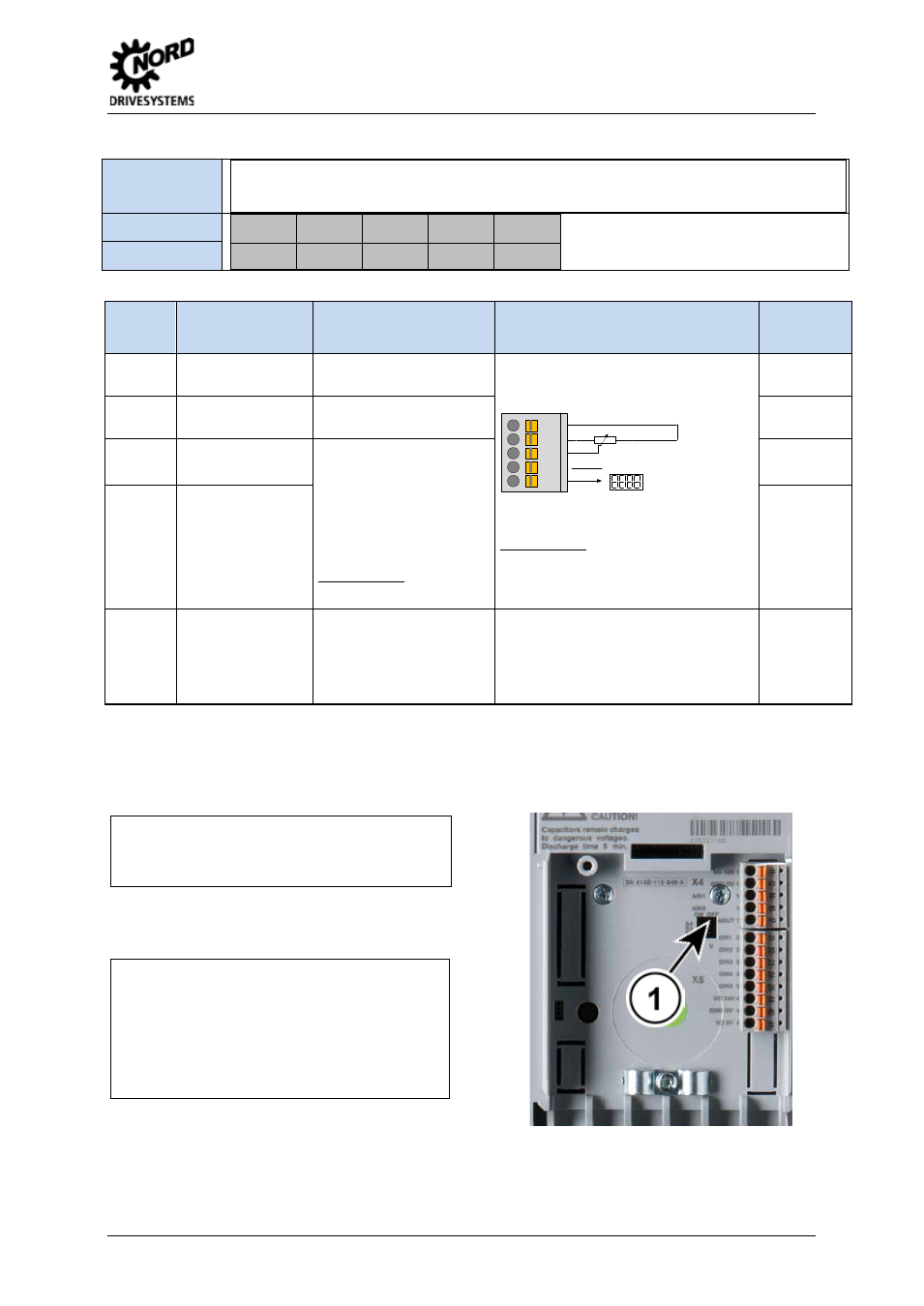
Configuration of analog signals
Size 1 … 4
1 = DIP switch: left = I / right = V
AIN2:
1
= Current 0/4 … 20 mA
V
= Voltage
AIN1:
1
= Current 0/4 … 20 mA
V
= Voltage
Above Size 5:
1 = DIP switch: left = ON / right = OFF
S4:
AIN2:
ON
= ± 10 V
OFF
= 0 … 10 V
S3:
AIN1:
ON
= ± 10 V
OFF
= 0 … 10 V
S2:
AIN2:
1
= ON = current 0/4...20 mA
V
= OFF = voltage
S1:
AIN1:
1
= ON = current 0/4...20 mA
V
= OFF = voltage
Note:
If S2 = ON (AIN2 = Current input), S4 must be = OFF.
If S1 = ON (AIN1 = Current input), S3 must be = OFF.
Pos : 61 /Anl eitungen/ Elektroni k/FU und Start er/ 2. M ont age und Ins tall ati on/ 2. 10. 5 Elektrischer Ansc hluss St euert eil- Klemmenbl oc k X5 – Digital In [SK 54xE] @ 2\ mod_1355475285848_388.doc x @ 52138 @ 5 @ 1