12 ratio control, Stoichiometric combustion, Ratio control – West Control Solutions Pro-EC44 User Manual
Page 88
Pro-EC44 2-Loop Graphical Profile Controller & Recorder
Pro-EC44 Product Manual - 59540-1 October 2013
Page 81
12 Ratio Control
A ratio control loop is used where the quantity of one of the material is to be controlled in
proportion to the measured quantity of a second material. The controller mixes the materials
at the desired ratio by adjusting the flow of input 1. The flow of input 2 may be controlled
separately, but is not controlled by the ratio control loop itself.
The process value used by the controller is therefore determined by the ratio of the two
inputs rather than a single measured variable.
Note: Ratio control is available on models with the 2
nd
Auxiliary Input, or two loop
models. The feature and information displayed is optimised for control of burner
fuel/air, but can be used in other flow ratio applications.
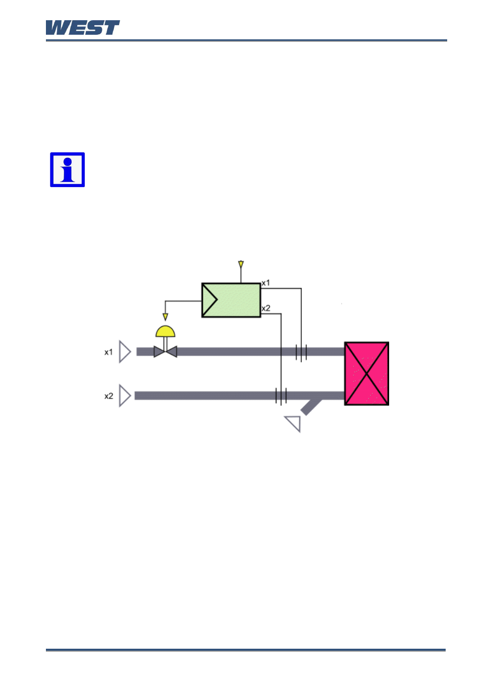
Stoichiometric Combustion
Below is an example of stoichiometric combustion ratio control. For optimum combustion the
fuel-air ratio is set so that there are no flammable residues in the waste gas.
Figure 48.
Ratio Control Example
It is normal in this application to display the process value and setpoint as relative values
rather than the physical ratio or absolute values. A scaling factor is set such that the
displayed value will be 1.00 at the correct stoichiometric ratio for the application.
Inputs 1 and 2 are configured and scaled to match the attached flow meters.
In this example a 4 to 20mA signal at x1 represents 0 to 1000m
3
/h of airflow controlled by a
valve. The second 4 to 20mA signal at x2 represents 0 to 100m3/h of fuel oil. The fuel flow is
not affected by this control loop.
Atomizing air is fed in with the fuel oil at a constant rate
‘NO’. This must be considered when
calculating the correct fuel/air mix. Total airflow is x1 + NO.
The stoichiometric factor, SFac is entered to match the desired ratio. E.g for 10 parts total
airflow to one part fuel, SFac would be 10.
The setpoint (entered as a relative value such as 1.00) is multiplied by SFac when
calculating the control deviation. E.g. with a setpoint of 1.00 and SFac of 10 the controller
Atomization Air
NO
Burner
Air
Fuel
Air Valve