Front panel operations, Step 7 — lan (ethernet) port, Step 8 — power on – Extron Electronics ISM 824 User Manual
Page 6
AC
T
LIN
K
LAN
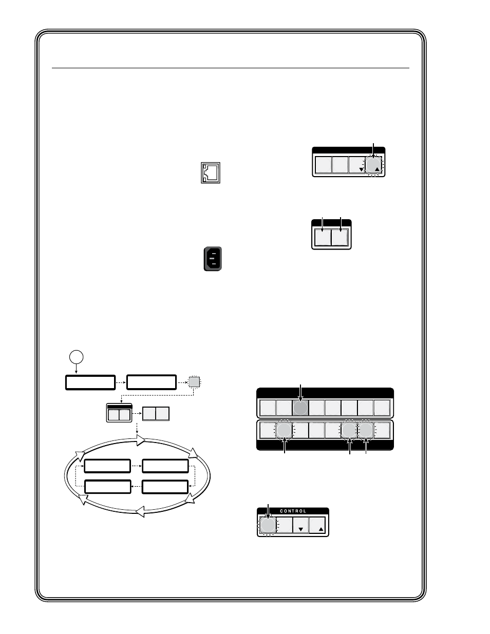
Figure Q-5 — Initial startup
sequence
Front Panel Operations
Making input to output ties
To make input ties to untied outputs:
1
. Press the Esc
button (clears
any changes
that may be
pending).
2
. If not already
lit, select the
Video button
(lights green),
Audio button
(lights red), or
both.
3
. Press (select)
the desired
input button.
Any existing tied output buttons light
(steady - green for video, red for audio,
or amber for both
). The LCD displays the
current ties.
4
. Press any untied (unlit) output buttons. The
output button flashes green red or amber to
indicate a tentative tie, and the Enter button
flashes green.
5
. Press the Enter button to make the tie. The
input, output, and Enter buttons extinguish.
chapter 3, “Operation and Setup”, “Front
section, for information about
adding, removing, or replacing ties.
I / O
C O N T R O L
PRESET
ENTER
ESC
VIEW
Step 1.
Press the Esc button.
Esc button flashes
green once
VIDEO AUDIO
When selected
Video button is lit
green, Audio button
is lit
red.
Step 2.
Press the Video or Audio button
or both to toggle on and off.
PRESET
ENTER
ESC
VIEW
1 2 3 4 5 6 7 8
1 2 3 4 5 6 7 8
OUTPUTS
INPUTS
After pressing
Enter button all lights extinguish.
Step 3.
Press and release desired Input button.
Step 5.
Press Enter button.
Step 4.
Press and release any desired Outputs.
The output buttons flash the appropriate color.
The
Enter button flashes green to indicate the
need to confirm the change.
ISM 824 Integration Scaling Multiswitcher • Quick Start
QS-2
Quick Start —
ISM 824 Integration Scaling Multiswitcher, continued
b
. If desired, connect a control system or
computer to the front panel Configuration
(RS-232) port. The optional 9-pin D
to 2.5 mm mini jack TRS RS-232 cable,
part #70-335-01, can be used for this
connection.
Step 7 — LAN (Ethernet) port
Connect a network WAN or LAN hub,
a control system, or a computer to the
Ethernet RJ-45 port. See
for details.
• Network connection — Wire as a patch
(straight) cable.
• Computer or control system connection —
Wire the interface cable as a crossover cable.
Step 8 — Power on
Plug the switcher into a grounded AC
source. Plug in and power on input and
output devices and the ISM 824. All front
panel buttons flash in sequence (red, green, and
amber). The Video and Audio buttons remain lit
(green and red), and the Menu and Next buttons
remain lit amber. All other buttons extinguish.
After powering up, the unit enters and displays
.
3
sec.
ISM 824
Version n.nn
1
sec.
Power
on
Extron
Electronics
All buttons
flash in
sequence.
3
sec.
1
sec.
I / O
AUDIO
VIDEO
Video and Audio
buttons remain lit.
2
sec.
2
sec.
Default Display Cycle
Card #1 Out 3/4
DualWideband
UnivScaler
Card #2 Out 5/6
Card #4 Out 8
Video Scaler
Card #3 Out 7
Wideband
2
sec.
2
sec.
N
The output cards shown in the default display cycle may
differ,depending on the type and number of cards installed.
MENU
NEXT
Menu and Next
buttons remain lit.
1
sec.