Installation, Step 4 — video outputs, Step 5 — audio outputs – Extron Electronics ISM 824 User Manual
Page 5: Step 6 — serial ports, Step 1, Step 2 — video inputs, Step 3 — audio inputs, Caution, Figure q-1 — video format for bnc connections, R/ r-y g/y b/ b-y h/ hv v
Quick Start — ISM 824
Integration Scaling Multiswitcher
H
/HV
RGBHV
Video
RGsB or
Component
Video
S-Video
Composite
Video
RGBS
Video
V
H/
HV
V
H/HV
V
H/HV
V
H/HV
V
R/R-Y
G/Y
VID
B/C
B-Y
R
/R-Y
G
/Y
VID
B
/C
B-Y
R
/R-Y
G
/Y
VID
B
/C
B-Y
R/R-Y
G/Y
VID
B
/C
B-Y
R/R-Y
G/
Y
VID
B/
C
B-Y
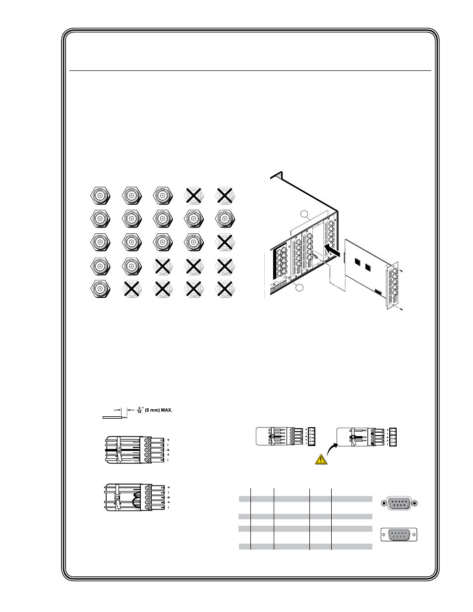
Figure Q-1 — Video format for BNC
connections
Step 4 — Video outputs
a
. Pass-through outputs — Connect video
devices to the BNC connectors for outputs
1 and 2. Connect cables as shown in figure
Q-1.
b
. Install any optional output boards (see
figure Q-3), and connect the relevant display
device to the BNC connectors on the boards.
See figure Q-1 for cabling format.
Figure Q-3 — Install Output cards
Step 5 — Audio outputs
Connect balanced or unbalanced stereo
audio or mono audio devices to the 5-pin
captive screw output connectors.
Step 6 — Serial ports
a
. If desired, connect a control system or
computer to the rear panel RS-232/RS-422
port.
Figure Q-2 — Audio connections
Figure Q-4 — Remote port pin
assignments
Unbalanced Stereo Output
CAUTION
For unbalanced audio, connect the sleeve(s) to
the center contact ground.
DO NOT
connect the
sleeve(s) to the negative (-) contacts.
Balanced Stereo Output
Tip
Ring
Sleeve(s)
Tip
Ring
L
R
Left
Right
Tip
NO GROUND HERE.
Sleeve(s)
Tip
NO GROUND HERE.
L
R
Left
Right
RS-232 Function
Pin
1
2
3
4
5
6
7
8
9
—
TX
RX
—
Gnd
—
—
—
—
Not used
Transmit data
Receive data
Not used
Signal ground
Not used
Not used
Not used
Not used
5
1
9
5
9
6
Female
Male
1
6
RS-422 Function
TX
RX
—
Gnd
—
RX+
TX+
—
Not used
Transmit data (-)
Receive data (-)
Not used
Signal ground
Not used
Receive data (+)
Transmit data (+)
Not used
—
100
- 24
0
50/60 Hz
1.2
A M
AX
.
1
2
3
4
5
6
7
8
2
1
2
3
4
5
6
7
8
1
2
1
INP
UT
S
OU
TPU
TS
R/R-Y
G/Y
VID
B/C
B-Y
H/HV
V
R/R-
Y
G/Y
VID
B/C
B-Y
H/HV
V
PA
SS
TH
RU
INP
UT
S
RE
SE
T
LA
N
R
E
M
O
TE
RS232/RS42
2
A
C
T
LINK
OUTP
UT
VID
EO
SC
AL
ER
70-5
45-0
1
3
R/
R-Y
G/Y
B/
B-Y
H/
HV
V
OUTP
UT
UN
IV.
SC
AL
ER
70-5
44-0
1
5
R/
R-Y
G/Y
B/
B-Y
H/
HV
V
OUTP
UT
PA
SS
TH
RU
70-5
47-0
1
8
R/
R-Y
G/Y
B/
B-Y
H/
HV
V
Extron
ISM 824
Integration Scaling
Multiswitcher
a
b
Align Output Card with
top and bottom plastic guides
of an open port.
Slide card in and secure
with screws.
R/
R-Y
G/Y
B/
B-Y
H/
HV
V
OUTP
UT
7
SC
AN
CO
NV
.
70-5
46-0
1
QS-1
ISM 824 Integration Scaling Multiswitcher • Quick Start
Installation
Step 1
Turn off power to the input and output devices,
and remove the power cords from them.
Step 2 — Video inputs
Inputs 1 through 8
— Connect RGB video,
component video, S-video, or composite
video to these female BNC connectors. See
below for format.
Step 3 — Audio inputs
Inputs 1 through 8
— Connect up to eight
stereo or mono audio inputs to the 5-pin
captive screw input connectors. Wire the
connectors as shown below.
Unbalanced audio
Balanced audio
Tip
Ring
Tip
Ring
L
R
Sleeves
Do not tin the wires!
Tip
Sleeve
Sleeve
Tip
L
R