An example of creating a set of i/o groups, An example of creating a set of i/o groups, Operation and setup, cont’d – Extron Electronics ISM 824 User Manual
Page 46
Operation and Setup, cont’d
ISM 824 Integration Scaling Multiswitcher • Operation and Setup
3-14
An example of creating a set of I/O groups
In the following example one of the four sets of I/O groups are set up. In this
example, input’s 3, 4, and 8, and outputs 2, 3, and 8, are to be assigned to I/O group
#2. All other buttons do not have a group assigned.
N
I/O buttons light green when pressed. Do not confuse this with video signal
only inputs or outputs that normally light green. Each input or output within a
group can transmit video only, audio only, or both.
1
.
Press Esc to clear all pending changes and reset the LCD (see figure 3-19).
2
.
Press and hold down the input and output buttons #1 simultaneously, for
around 3 seconds (see figure 3-19). Those two buttons and the Enter button
will stop flashing. All ungrouped buttons light steady green and the LCD
screen displays the currently grouped input and output buttons, by their
group number.
N
In this example input #2 and output #’s 1, 5, and 7, have already been added to
group #1. The remaining ungrouped buttons light green, and the LCD displays
“1” for grouped, and “0” for ungrouped inputs and outputs.
C O N T R O L
PRESET
ENTER
ESC
VIEW
1 2 3 4 5 6 7 8
1 2 3 4 5 6
8
OUTPUTS
INPUTS
7
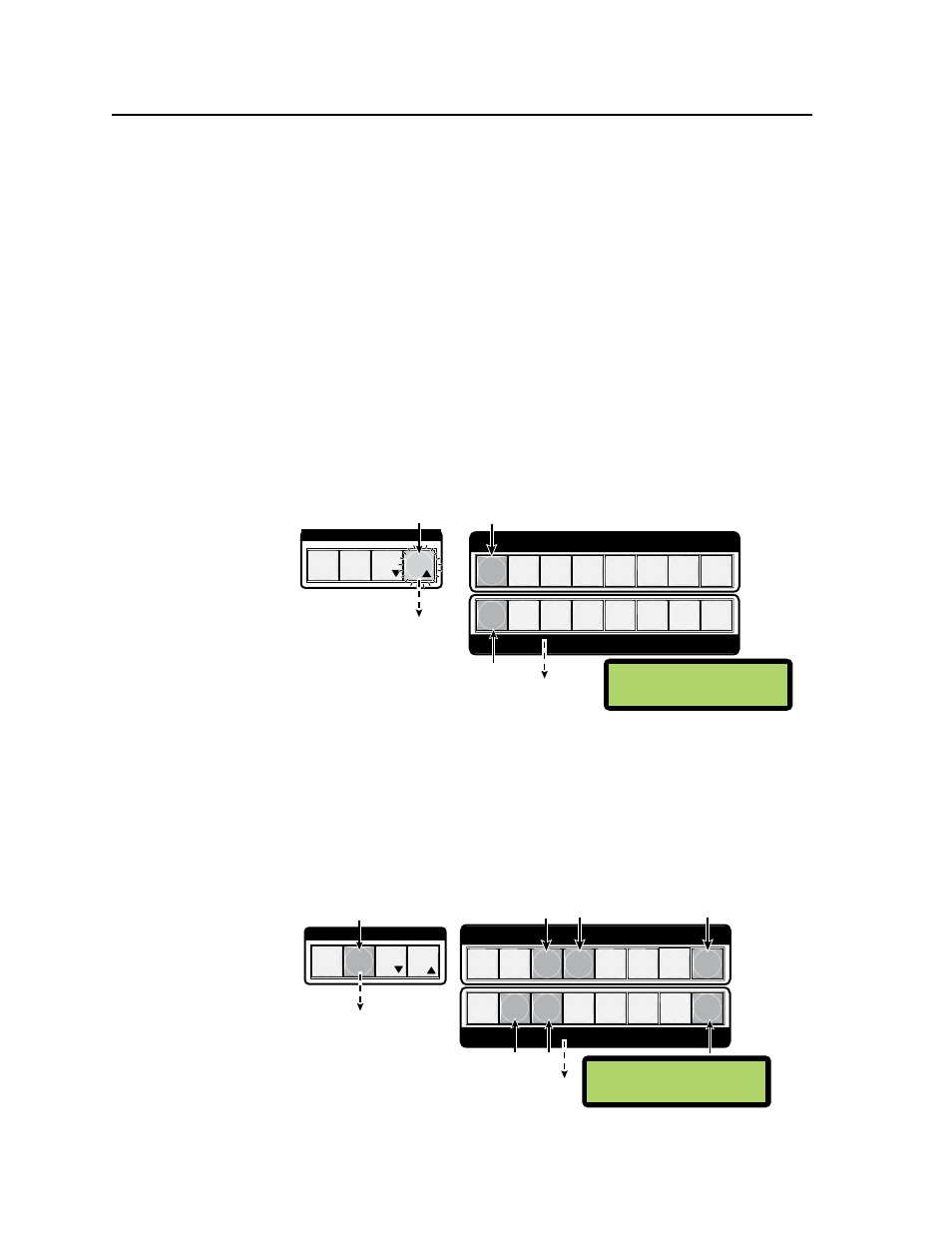
Step 1.
Press the Esc button to
clear all selections.
Step 2.
Press and
hold Input button 1 and Output
button 1 for three seconds.
N
The LCD shows the
current
I/O grouping.
O
ut
G
rp
10001010
I
n
G
rp
01000000
The Esc button
flashes
green once.
The input and output buttons stop
flashing
green, and all ungrouped
buttons light
green. The Enter
button extingiushes
Figure 3-19 — Steps 1 and 2 for creating I/O grouping
3
.
To add inputs and outputs to group #2 (for example), press the Preset
button (see figure 3-20). This lights amber and all input and output buttons
extinguish.
4
. Select input buttons 3, 4, and 8, and output buttons 2, 3, and 8
(see figure 3-20). These all light green.
C O N T R O L
ENTER
ESC
VIEW
1 2 3 4 5 6 7 8
1 2 3 4 5 6
8
OUTPUTS
INPUTS
7
PRESET
Step 3.
Press the Preset button
to select I/O group #2.
Step 4.
Press input buttons 3, 4, and 8, and
output buttons 2, 3, and 8.
N
The LCD now shows
I/O groups #1 and #2.
O
ut
G
rp
12201012
I
n
G
rp
01220002
The input and output
buttons light
green.
The Preset button lights
amber. All lit input and
output buttons extinguish.
Figure 3-20 — Steps 3 and 4 for creating I/O grouping